
Power relay equipment for insulating building

A technology for relays and construction, applied in the direction of electromagnetic relays, relays, detailed information of electromagnetic relays, etc., can solve the problems of reduced performance, dry surface of insulating paint, pollution of the environment, etc., and achieve good mechanical properties, good insulation performance, paint film even surface effect

Inactive Publication Date: 2017-03-22
芜湖浩权建筑工程有限公司
View PDF5 Cites 5 Cited by
  • Summary
  • Abstract
  • Description
  • Claims
  • Application Information

AI Technical Summary

Problems solved by technology

The working principle of the general electromagnetic relay is similar to that of the monostable trigger circuit. Its disadvantage is that the coil must have a maintaining current to keep the contacts in the required state.
However, in actual production, solvent-based paints also contain solvents and have a lower solid content than solvent-free paints, so the drying time is longer, which will bring longer waiting times for actual use, and greatly Affect production efficiency
At the same time, because most insulating varnishes may be used for a long time in actual use, due to moisture reduction or environmental changes, the surface of the insulating varnish will dry and crack, and then the performance will be reduced.
[0004] At present, several types of insulating varnishes commonly used have their shortcomings: traditional solvent-based insulating varnishes will have a large amount of organic solvents volatilized during the curing process, polluting the environment; and solvent-free insulating varnishes and high-solid insulating varnishes There are problems of small output and high production cost, which cannot meet market demand

Method used


Image

  • Power relay equipment for insulating building

Examples


Embodiment 1

[0031] S1. Weigh 35 parts of bismaleimide resin, 22 parts of aluminum hydroxide, 33 parts of polyethylene elastomer, 11 parts of epoxy resin, 8 parts of diphenyldichlorosilane, and 15 parts of styrene 5 parts, 5 parts of cyclohexanone peroxide, 4 parts of m-p-cresol, and 3 parts of submicron quartz powder were poured into a heated electric stirring device, and stirred at a speed of 350 r / min for 9 minutes at a temperature of 90 ° C; the mixture was obtained ;

[0032] S2. Add 6 parts of vulcanizing agent, 6 parts of defoamer, 5 parts of co-solvent, 5 parts of film-forming agent and 4 parts of curing agent into the mixture in step S1, and stir at 350 r / min for 5 minutes at a temperature of 100 °C ; Obtain insulating varnish material;

[0033] S3. Use an electric polishing machine to polish the surface of the insulating shell, evenly coat the insulating varnish material prepared in step S2 on the insulating shell, dry it in a high-temperature drying oven for 60 minutes, and the...

Embodiment 2

[0035] S1. Weigh 40 parts of bismaleimide resin, 25 parts of aluminum hydroxide, 35 parts of polyethylene elastomer, 15 parts of epoxy resin, 10 parts of diphenyldichlorosilane, and 16 parts of styrene Parts, 9 parts of cyclohexanone peroxide, 15 parts of m-p-cresol, and 4 parts of submicron quartz powder were poured into a heated electric stirring device, and stirred at a speed of 350r / min for 12min at a temperature of 100°C; the mixture was obtained ;

[0036]S2. Add 6 parts of vulcanizing agent, 6 parts of defoamer, 5 parts of co-solvent, 5 parts of film-forming agent and 4 parts of curing agent into the mixture in step S1, and stir at 350r / min for 5min at a temperature of 100°C ; Obtain the insulating varnish material;

[0037] S3. Use an electric polishing machine to polish the surface of the insulating shell, evenly coat the insulating varnish material prepared in step S2 on the insulating shell, dry it in a high-temperature drying oven for 60 minutes, and then let it s...

Embodiment 3

[0039] S1. Weigh 30 parts of bismaleimide resin, 20 parts of aluminum hydroxide, 30 parts of polyethylene elastomer, 8 parts of epoxy resin, 6 parts of diphenyldichlorosilane, and 11 parts of styrene 1 part, 4 parts of cyclohexanone peroxide, 2 parts of m-p-cresol, and 1 part of submicron quartz powder were poured into a heated electric stirring device, and stirred at a speed of 300 r / min for 6 min at a temperature of 80 ° C; the mixture was obtained ;

[0040] S2. Add 2 parts of vulcanizing agent, 2 parts of defoamer, 2 parts of co-solvent, 1 part of film-forming agent and 2 parts of curing agent into the mixture in step S1, and stir at 300r / min for 2min at a temperature of 80°C ; Obtain the insulating varnish material;

[0041] S3. Use an electric polishing machine to polish the surface of the insulating casing, evenly coat the insulating varnish material prepared in step S2 on the insulating casing, dry it in a high-temperature drying oven for 40 minutes, and then let it s...


PUM


Abstract

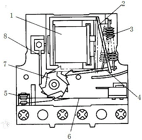
The invention discloses power relay equipment for an insulating building. The power relay equipment comprises a base, a coil, an armature, a restoring spring, a push rod, contacts, a lower plate spring, a middle ratchet wheel and an upper plate spring, wherein an insulating shell is arranged above the base; an iron core is arranged in the insulating shell through a bracket; the coil is arranged on the iron core; the bracket is connected with the restoring spring. The power relay equipment for the insulating building, disclosed by the invention, is simple in structure and convenient to operate; the armature attracts the iron core under the action of electromagnetic attraction to drive the push rod to rotate the middle ratchet wheel anticlockwise; the plate springs move, so that a contact state of upper and lower layers of the contacts is changed; when driving electric pulse disappears, the armature returns to an initial state under the action of the restoring spring, a ratchet abuts against a tooth surface on a seedling wheel and the ratchet wheel does not rotate, so that the contacts can keep the state unchanged; only if the quantity of teeth and tooth shapes of upper and lower layers of ratchet wheels are changed, 2 to 4 steps form one cycle of 1 to 2 contacts, and different control functions are realized.

Description

technical field [0001] The invention relates to a power relay device for insulating buildings. Background technique [0002] The stepping relay is also an electromagnetic relay, but its working method is quite different from that of a general electromagnetic relay. When the coil of a general electromagnetic relay is energized, its contacts will move, and the contacts will change from normally open to closed or from normally closed to open. In order to maintain this state, there must be a certain maintenance current in the relay coil. If the current of the coil is disconnected, the relay will be released and the contacts will return to their original state. The working principle of the general electromagnetic relay is similar to that of the monostable trigger circuit. Its disadvantage is that the coil must have a maintaining current to keep the contacts in the required state. [0003] Insulating varnish is widely used in daily production because electric power and other p...

Claims


Application Information

Patent Timeline
IPC IPC(8): C09D151/08C09D123/04C09D163/00C09D7/12C09D5/25C08F283/04C08F212/08H01H50/32H01H50/02
CPCC09D151/08C08F283/045C08L2203/20C08L2205/03C09D7/61C09D7/63H01B3/307H01H50/02H01H50/32C08L23/04C08L63/00C08K13/02C08K2003/2227C08K5/54C08K5/13C08K3/36C08F212/08
Inventor 胡圣武
Owner 芜湖浩权建筑工程有限公司
Learn More