Hydraulic system for pile driving barge
A technology of hydraulic system and piling ship, applied in the field of hydraulic system, can solve problems such as large pressure shock, and achieve the effects of small pressure shock, low vibration and noise, and stable depressurization process
- Summary
- Abstract
- Description
- Claims
- Application Information
AI Technical Summary
Problems solved by technology
Method used
Image

Examples
Embodiment 1
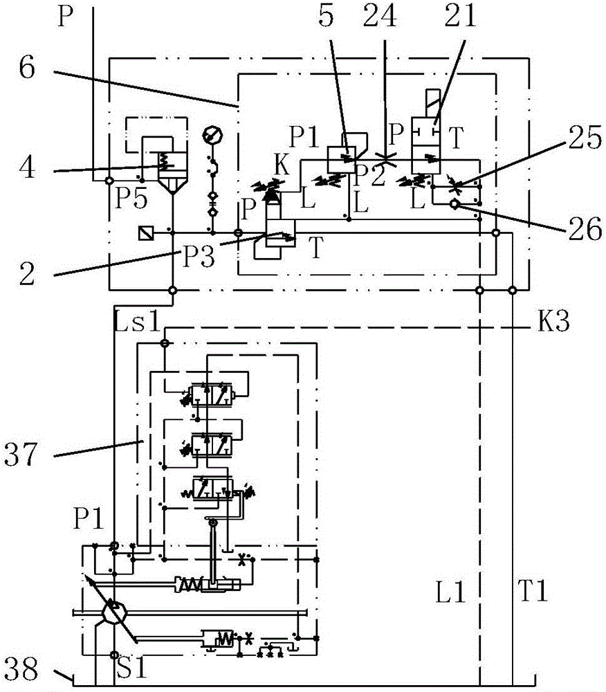
[0037] Such as figure 1 As shown, the hydraulic system for the piling ship in Embodiment 1 of the present invention includes a hydraulic pump oil supply circuit, and the hydraulic pump oil supply circuit includes two pressure and power compound control variable pumps, and the two pressure and power compound control The variable pumps are connected in parallel, and the oil ports on the oil discharge pipelines of the two pressure and power compound controlled variable pumps are each connected in parallel with a pressure buffer control valve group; the pressure buffer control valve group includes a first pilot relief valve 2. The first decompression valve 5, the first fixed orifice 24, the first adjustable orifice 25, the first one-way valve 26 and the first electromagnetic reversing valve 21;
[0038] The structure and connection method of the two pressure and power compound control variable pumps are the same, and the structure, technical parameters and connection method of the...
Embodiment 2
[0041] Such as figure 1 As shown, the hydraulic system for the piling ship in Embodiment 2 of the present invention includes a hydraulic pump oil supply circuit, and the hydraulic pump oil supply circuit includes two pressure and power compound control variable pumps, and the two pressure and power compound control The variable pumps are connected in parallel, and the oil ports on the oil discharge pipelines of the two pressure and power compound controlled variable pumps are each connected in parallel with a pressure buffer control valve group; the pressure buffer control valve group includes a first pilot relief valve 2. The first decompression valve 5, the first fixed orifice 24, the first adjustable orifice 25, the first one-way valve 26 and the first electromagnetic reversing valve 21;
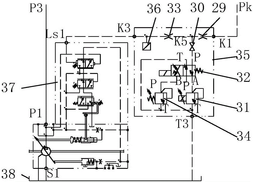
[0042] Such as figure 2 As shown, the hydraulic pump oil supply circuit also includes a load sensitive pressure control valve group, the load sensitive pressure control valve group is c...
Embodiment 3
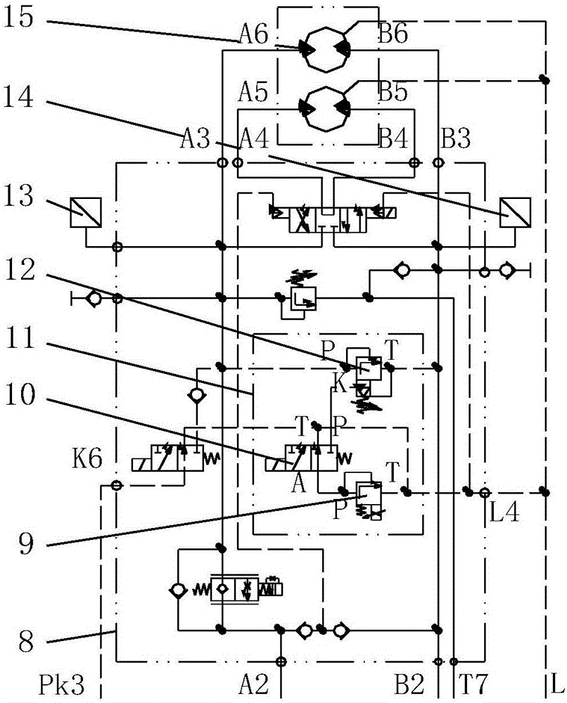
[0046] Such as Figures 1 to 4 As shown, the hydraulic system for piling ships in Embodiment 3 of the present invention includes a hydraulic pump oil supply circuit, a ship-moving winch control circuit, and a pile frame luffing hydraulic cylinder control circuit; The oil circuit generally includes the fuel tank, the main oil supply circuit, the total pressure oil circuit, the total oil drain circuit, the total oil return circuit and the hydraulic control circuit, specifically including the control oil main pipe Pk, the oil return main pipe T, the oil drain main pipe L and the pressure oil Manager P et al.
[0047] The oil supply circuit of the hydraulic pump is composed of two pressure and power compound control variable pumps 28 and 37, the pressure buffer control valve groups 6 and 23, the load sensitive pressure control valve groups 27 and 35 to which the above variable pumps belong respectively; and one The constant pressure variable pump 1 and its associated electromagne...
PUM
 Abstract
Description
Claims
Application Information
 - R&D
- Intellectual Property
- Life Sciences
- Materials
- Tech Scout
- Unparalleled Data Quality
- Higher Quality Content
- 60% Fewer Hallucinations
Browse by: Latest US Patents, China's latest patents, Technical Efficacy Thesaurus, Application Domain, Technology Topic, Popular Technical Reports.
© 2025 PatSnap. All rights reserved.Legal|Privacy policy|Modern Slavery Act Transparency Statement|Sitemap|About US| Contact US: help@patsnap.com