F-P micro-cavity fiber sensor and manufacturing method thereof
A technology of optical fiber sensor and manufacturing method, applied in the direction of converting sensor output, using optical devices to transmit sensing components, instruments, etc., can solve the problems of difficult to accurately control the cavity length, complex assembly process, poor repeatability, etc., to ensure integrity , short processing cycle and low cost
- Summary
- Abstract
- Description
- Claims
- Application Information
AI Technical Summary
Problems solved by technology
Method used
Image
Examples
Embodiment 1
[0037] Embodiment 1: A reflective surface is a flat processing method
[0038] (1) Use a cleaver to cut an end face of the optical fiber as a mirror of the F-P microcavity;
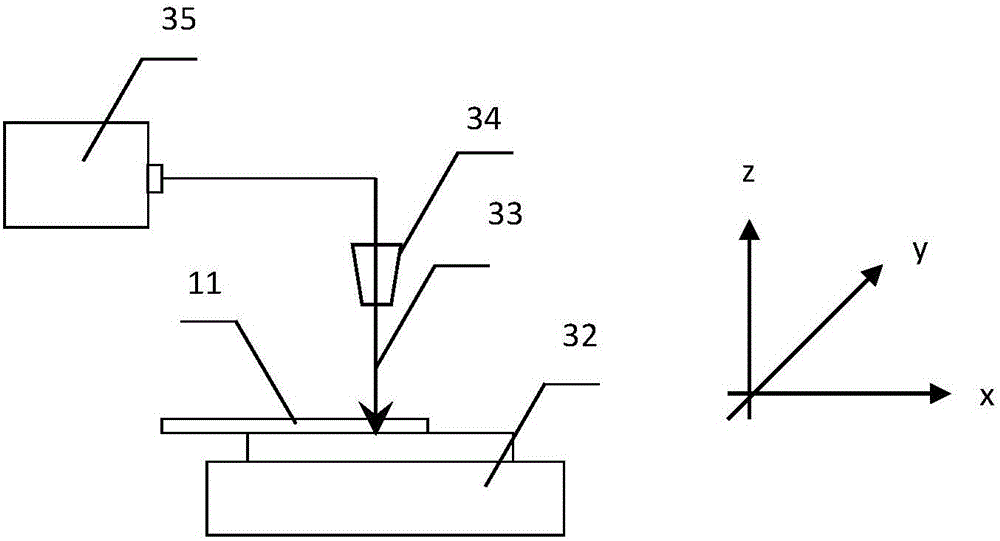
[0039] (2) Place the optical fiber on a three-dimensional mobile platform so that the axis of the optical fiber is perpendicular to the incident direction of the laser;
[0040] (3) According to the F-P microcavity parameter requirements, adjust the three-dimensional mobile platform to determine the cavity length;
[0041] (4) Make the laser focus on the core of the fiber through the objective lens of the microscope, feed the laser energy, and form a modulation point of the refractive index at the laser focusing part in the fiber to form another mirror of the F-P microcavity.
[0042] Such as figure 1 As shown, the optical fiber microsensor made is characterized in that it includes a single-mode optical fiber (11), a second reflective mirror (13) on the end face of the single-mode optical fiber cut flat...
Embodiment 2
[0043] Embodiment 2: A reflective surface is a tapered processing method
[0044] (1) Use a fusion splicer to extend the optical fiber into a tapered shape as a mirror of the F-P microcavity;
[0045] (2) Place the optical fiber on a three-dimensional mobile platform so that the axis of the optical fiber is perpendicular to the incident direction of the laser;
[0046] (3) According to the F-P microcavity parameter requirements, adjust the three-dimensional mobile platform to determine the cavity length;
[0047] (4) Make the laser focus on the core of the fiber through the objective lens of the microscope, feed the laser energy, and form a modulation point of the refractive index at the laser focusing part in the fiber to form another mirror of the F-P microcavity.
[0048] Such as figure 2 As shown, the present embodiment is basically the same as the first embodiment, and the special feature is that the second reflective mirror surface (22) is a tapered microsensor, and a...
Embodiment 3
[0049] Embodiment 3: Fabrication of a fiber optic microsensor based on an F-P microcavity
[0050] (1) Place the optical fiber with the end face cut flat on the three-dimensional mobile platform;
[0051] (2) Adjust the three-dimensional mobile platform so that the axis of the optical fiber is perpendicular to the incident direction of the laser;
[0052] (3) Adjust the three-dimensional mobile platform to determine the cavity length;
[0053] (4) Make the laser focus on the core of the fiber through the objective lens of the microscope, feed the laser energy, and form a modulation point of the refractive index at the laser focusing part in the fiber to form another mirror of the F-P microcavity.
[0054] Such as figure 1As shown, the characteristics of the optical fiber microsensor made are that the optical fiber (11) is placed on the three-dimensional mobile platform (32), so that the axis of the optical fiber (11) is perpendicular to the incident direction of the laser be...
PUM
 Abstract
Description
Claims
Application Information
 - Generate Ideas
- Intellectual Property
- Life Sciences
- Materials
- Tech Scout
- Unparalleled Data Quality
- Higher Quality Content
- 60% Fewer Hallucinations
Browse by: Latest US Patents, China's latest patents, Technical Efficacy Thesaurus, Application Domain, Technology Topic, Popular Technical Reports.
© 2025 PatSnap. All rights reserved.Legal|Privacy policy|Modern Slavery Act Transparency Statement|Sitemap|About US| Contact US: help@patsnap.com


