Vacuum high-speed camera system for ground separation and deployment tests of spacecraft components

A high-speed camera and high-speed camera technology, applied in the field of camera systems, can solve the problems of lack of zoom, focus, aperture adjustment, difficulty for operators, low flexibility, etc., to improve the level of visualization, low failure rate, and good safety. Effect

Active Publication Date: 2019-04-02
BEIJING INST OF SPACECRAFT ENVIRONMENT ENG
View PDF4 Cites 0 Cited by
  • Summary
  • Abstract
  • Description
  • Claims
  • Application Information

AI Technical Summary

Problems solved by technology

[0008] Usually, high-speed cameras are designed with replaceable lenses. The lenses are generally adjusted manually and do not have the functions of zooming, focusing, and aperture adjustment remotely. This leads to the fact that when the camera is installed in the tooling, the operator cannot adjust it. Especially for large-scale tests such as fairings, the tooling often needs to be installed on the top of the ring die equipment, and it is difficult for the operator to set the lens parameters before installation, resulting in the need to disassemble the equipment multiple times to adjust the lens parameters
[0009] At present, there are Chinese patents "CN201410236278 Digital HD Network Camera and Its System for Thermal Vacuum Environment" and "CN201310232470 A Camera System Suitable for Vacuum and Cryogenic Environments" about the vacuum camera system. These two patents are mainly aimed at High-definition (above 720P), low-speed (generally less than 30Fps) monitoring and recording of the test piece under the vacuum low-temperature system does not have the recording capability of 500 fps or above, and only the replacement of the camera cannot meet the requirements of remote re-zooming of the high-speed camera electric lens , focusing requirements, low flexibility, needs to be customized for each test, and cannot meet the current vacuum separation and deployment tests of various spacecraft represented by fairings and balloon deployment lights

Method used


Image

  • Vacuum high-speed camera system for ground separation and deployment tests of spacecraft components
  • Vacuum high-speed camera system for ground separation and deployment tests of spacecraft components
  • Vacuum high-speed camera system for ground separation and deployment tests of spacecraft components

Examples


Embodiment Construction

[0026] The vacuum camera system for vacuum environment simulation equipment of the present invention will be described in detail below with reference to the accompanying drawings, but the description is only exemplary and not intended to limit the protection scope of the present invention.

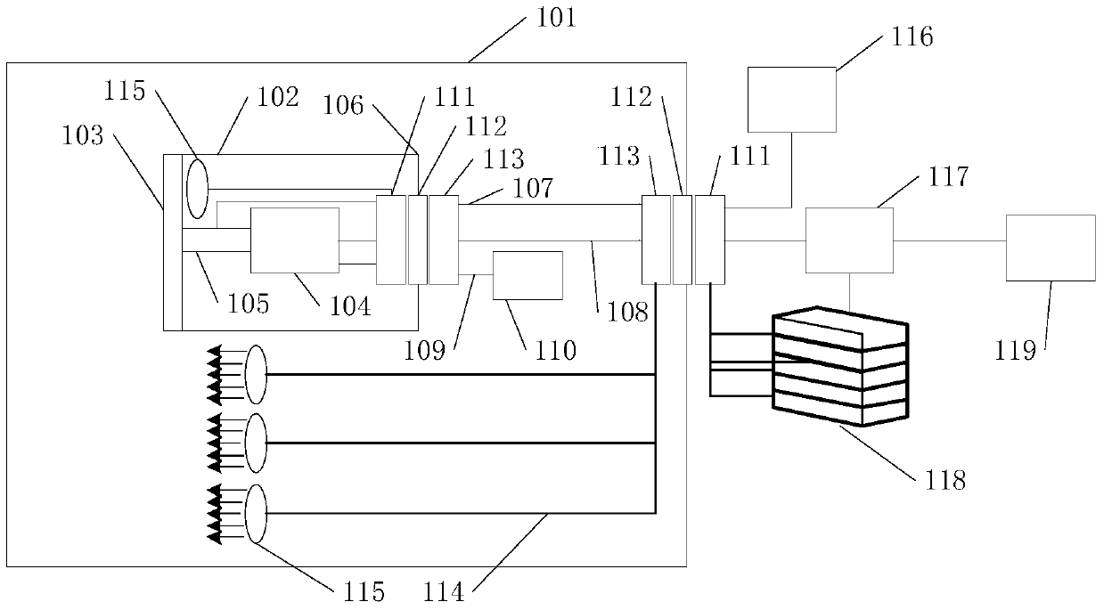
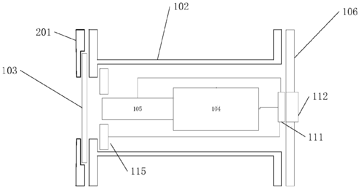
[0027] Such as figure 1 It is the principle diagram of the vacuum high-speed camera system of the present invention, as shown in the figure 101 is a vacuum environment simulation equipment, the inside is a vacuum environment (<10-3Pa), and the outside is a normal temperature and normal pressure environment, wherein the camera cabin 102, the outside of the cabin LED array 115 etc. can be installed in its cabin, gigabit switchboard 117, program-controlled DC power supply 118, control computer 119 etc. are installed outside the cabin; Less than 10^-7Pa L / S; 103 is the quartz glass at the front of the cylinder, which is compressed by the front flange; 104 is a high-speed camera, which is a sta...


PUM


Abstract

The invention provides a vacuum high-speed image photographing system for ground separation and experiment carrying-out of a spacecraft component. The invention discloses the vacuum high-speed image photographing system for analog equipment in a vacuum environment. The vacuum high-speed image photographing system comprises the components of a high-speed image camera, a remote electric ternary variable lens, an airtightness protecting tool, an LED lamp array, a portable display device, electric connectors, etc. The image camera is a standard lens-interchangeable high-speed image camera. The remote electric ternary variable lens realizes remote operation capabilities of focal length adjustment and aperture focusing on a camera. The airtightness protecting tool satisfies an airtight function. The leakage rate of the airtightness protecting tool is lower than 10<-7>Pa*L / S. The LED lamp array is composed of a plurality of high-power LED lamps. A programmable power supply is used for controlling the LED lamps. A control terminal performs direct control and comprises a control computer and a lens control terminal. A requirement for remote control capability for various parameters of the camera and the lens can be satisfied. Furthermore a remote switching capability for the LED lamp is realized.

Description

technical field [0001] The invention belongs to the technical field of vacuum separation and deployment tests on the ground of spacecraft, and in particular relates to a camera system for ground separation and deployment tests of spacecraft components. Background technique [0002] With the continuous improvement of my country's spacecraft model development requirements, more and more models have put forward the need for video surveillance in special environments such as vacuum, especially for fairings that are rapidly deployed and unlocked in orbit, and explosive unlocking devices. It satisfies the demand for high-speed imaging of the full size of the specimen at a frame rate of 500 fps or more under vacuum with a large viewing angle. [0003] Since the general speed of the spacecraft separation and deployment test can reach more than 5m / s, and the test time is generally within 1s, in order to reduce the influence of ground air resistance, it is usually carried out in the sp...

Claims


Application Information

Patent Timeline
Patent Type & Authority Patents(China)
IPC IPC(8): H04N7/18G03B39/00
Inventor 李西园简亚彬孙嘉明李培印杜春林孙玉玮裴一飞张春华
Owner BEIJING INST OF SPACECRAFT ENVIRONMENT ENG
Why Eureka
Try Eureka