Vortex permanent magnet expander and waste heat recovery power generation system using the expander
An expander, permanent magnet technology, applied in the direction of machines/engines, mechanical equipment, engine components, etc., can solve the problems of increased working temperature of generators, poor power generation efficiency and thermal efficiency, increased exhaust superheat and condenser load, etc. , to reduce outlet superheat, improve performance and improve cooling efficiency
- Summary
- Abstract
- Description
- Claims
- Application Information
AI Technical Summary
Problems solved by technology
Method used
Image
Examples
Embodiment 1
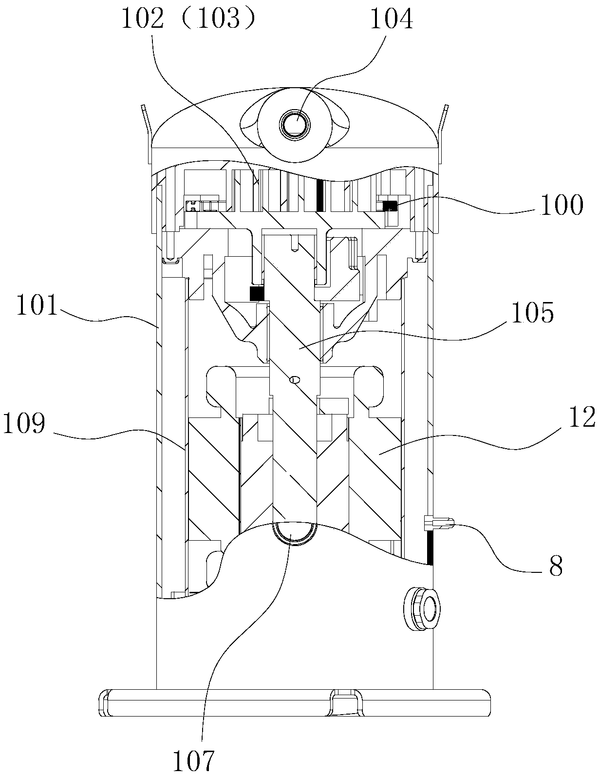
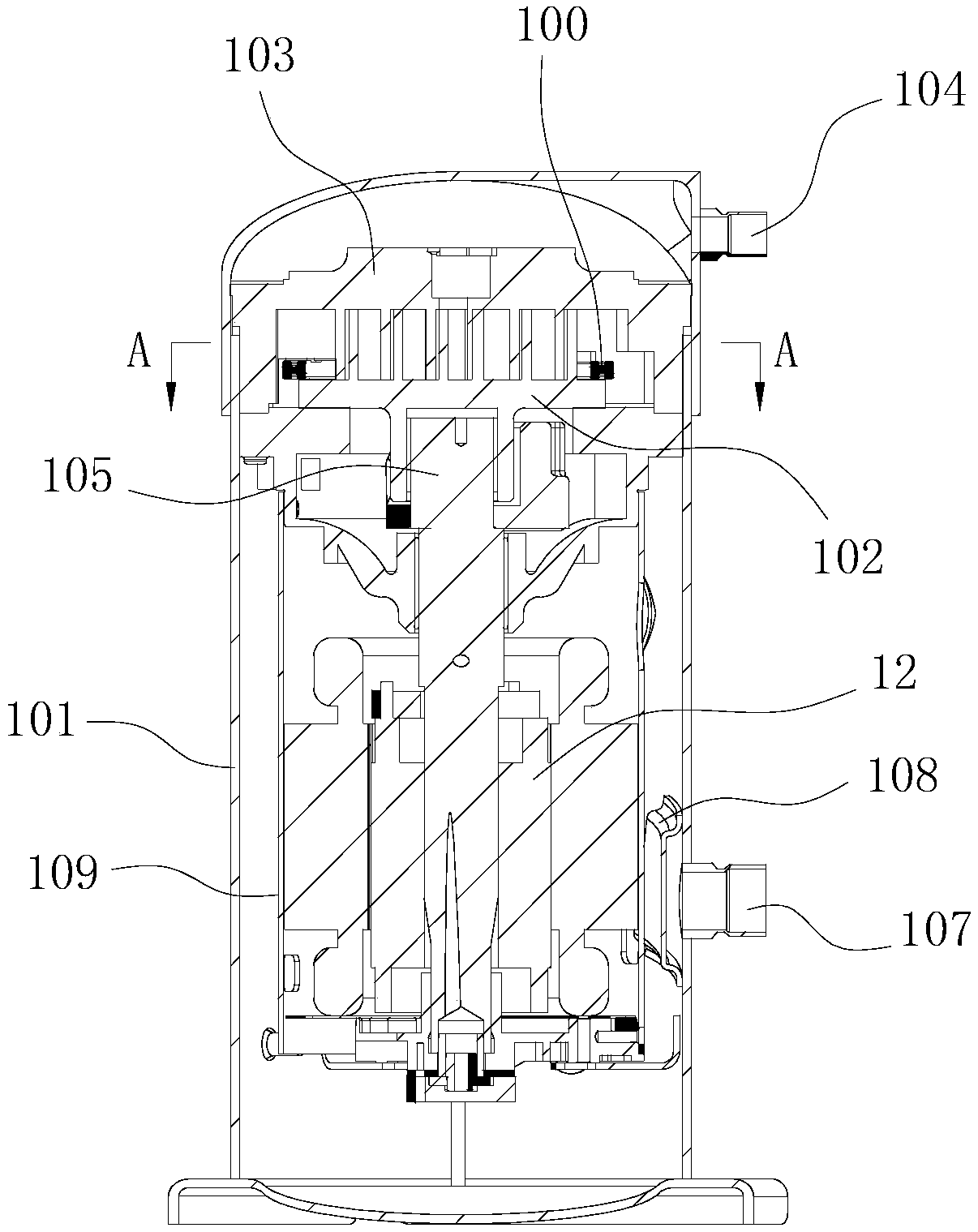
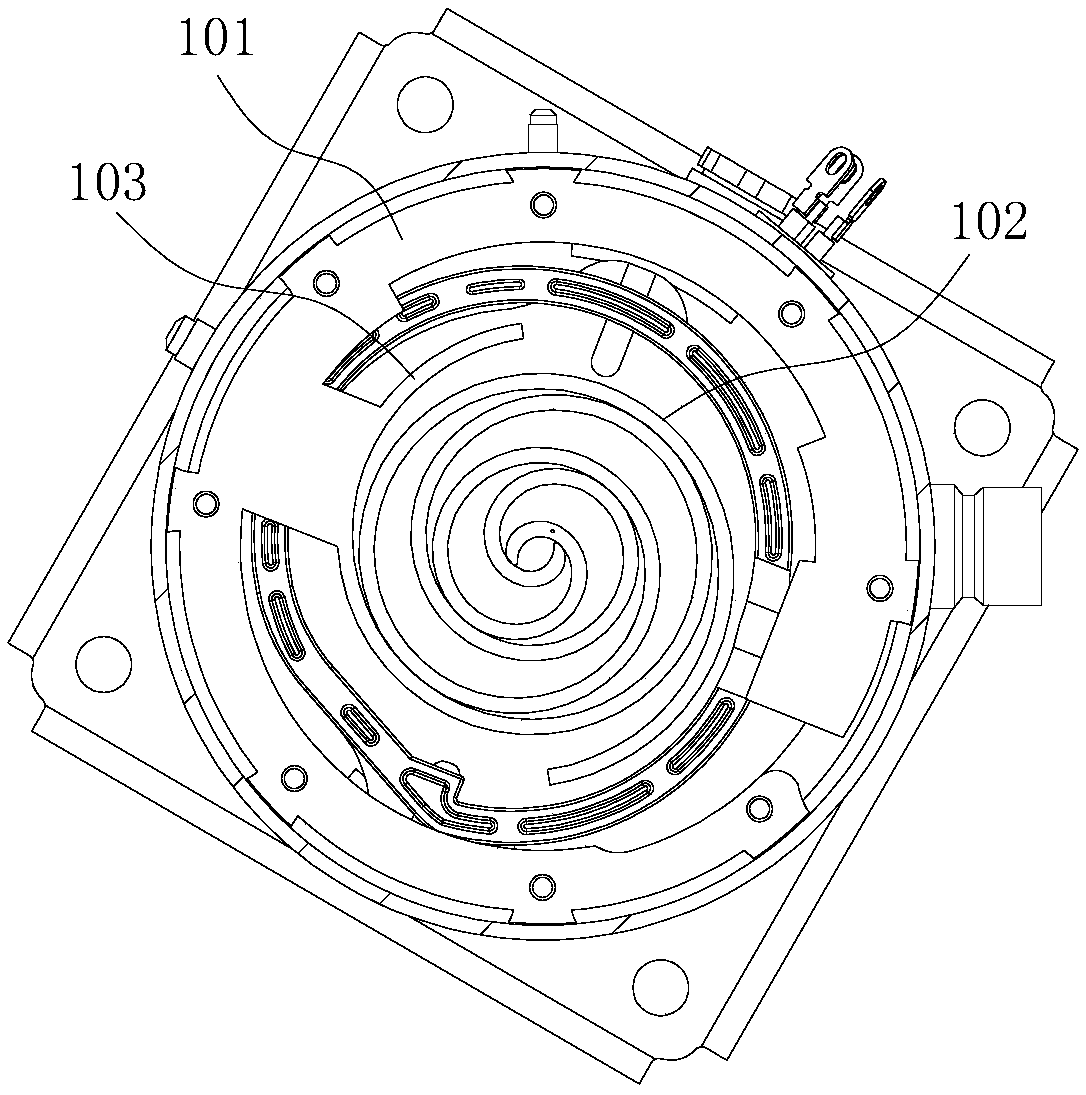
[0031] Such as figure 1 , 2 , 3, a scroll permanent magnet expander, including the movable scroll 102, fixed scroll 103, eccentric shaft 105 and generator 12 arranged in the casing 101, the movable scroll 102 and the fixed scroll The scrolls 103 are interlocked to form the expansion mechanism 11, and the movable scroll 102 is connected to the main shaft of the generator 12 through the eccentric shaft 105, so that the movable scroll 102 can revolve around the center of the fixed scroll 103, and the movable scroll The disk 102 is also provided with a limiting device for preventing the movable scroll 102 from rotating; The center expands outward along the spiral path, and pushes the movable scroll 102 to revolve. The movable scroll 102 drives the main shaft of the generator 12 to rotate through the eccentric shaft 105. The electric energy generated by the generator 12 is used by the load 2; An exhaust port 107 is opened on the top to discharge, and an organic working medium liq...
Embodiment 2
[0036] Such as Figure 4 , 5 As shown, a waste heat recovery power generation system containing the vortex permanent magnet expander includes a condenser 3, a working medium pump 4, an evaporator 5 and the vortex permanent magnet expander 1, and the evaporator 5 The outlet end of the evaporator is connected to the vortex permanent magnetic expander 1, the condenser 3 and the working medium pump 4 in turn through the pipeline, and is connected to the inlet end of the evaporator 5 through the working medium pump 4 to form an organic Rankine cycle. In the organic Rankine cycle, a branch pipe is arranged on the pipeline between the working medium pump 4 and the evaporator 5, and the branch pipe is used as the liquid injection pipeline 10; the liquid injection pipeline and the scroll permanent magnetic expander 1 The organic working medium spray port 8 communicates.
[0037] Preferably, the liquid injection pipeline 10 is also provided with a liquid injection electromagnetic valv...
PUM
 Abstract
Description
Claims
Application Information
 - R&D Engineer
- R&D Manager
- IP Professional
- Industry Leading Data Capabilities
- Powerful AI technology
- Patent DNA Extraction
Browse by: Latest US Patents, China's latest patents, Technical Efficacy Thesaurus, Application Domain, Technology Topic, Popular Technical Reports.
© 2024 PatSnap. All rights reserved.Legal|Privacy policy|Modern Slavery Act Transparency Statement|Sitemap|About US| Contact US: help@patsnap.com


