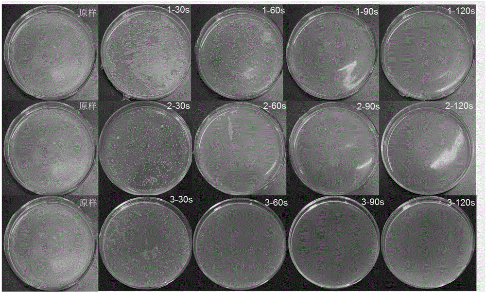
Plasma water processing system

A water treatment system, plasma technology, applied in the direction of plasma, light water/sewage treatment, electrical components, etc., can solve the problems of cumbersome maintenance, high cost, complexity, etc., achieve broad application prospects, reduce environmental damage, temperature low effect

Pending Publication Date: 2017-02-22
DALIAN NATIONALITIES UNIVERSITY
View PDF6 Cites 7 Cited by
  • Summary
  • Abstract
  • Description
  • Claims
  • Application Information

AI Technical Summary

Problems solved by technology

Most atmospheric pressure low-temperature plasma water treatment devices need to use complex gas paths or electrode arrangements, which makes plasma water treatment devices more complicated, often resulting in high costs, cumbersome maintenance, and various problems emerge in endlessly

Method used


Image

  • Plasma water processing system
  • Plasma water processing system
  • Plasma water processing system

Examples


Embodiment 1

[0032] Such as figure 1As shown, the first cavity of the dielectric box is a cube structure with a length, width and height of 1100mm, and a wall thickness of 100mm, forming a hollow cavity with a side length of 900mm, and the cavity is made of polytetrafluoroethylene. The distance between the water inlet pipe and the upper surface of the cavity is 200mm, and the distance between the water outlet pipe and the upper surface of the chamber is 230mm. The outer diameter of the water inlet and outlet pipes is 300mm, the wall thickness is 50mm, and the inner diameter is 200mm. , The outlet pipe is made of quartz material. Both the first PCB board and the second PCB board are in the shape of a cuboid with a length of 1100mm, a width of 300mm, and a thickness of 10mm. A gasket is adhered between the PCB board and the cavity of the dielectric body. The thickness of the gasket is 5mm to ensure that the first PCB board and the second PCB board The vertical distance between the average P...

Embodiment 2

[0034] Such as image 3 As shown, the first cavity of the dielectric box is a rectangular parallelepiped structure with a length and width of 200mm, a height of 500mm, and a wall thickness of 25mm, forming a hollow cavity of 150mm*150mcm*450mm. The cavity is made of plexiglass. The distance between the water inlet pipe and the upper surface of the cavity is 50mm, and the distance between the water outlet pipe and the upper surface of the chamber is 200mm. The outer diameter of the water inlet and outlet pipes is 100mm, the wall thickness is 15mm, and the inner diameter is 70mm. , The outlet pipe is made of corrosion-resistant plastic. Both the first PCB board and the second PCB board are in the shape of a cuboid with a length of 500mm, a width of 50mm, and a thickness of 2mm. A gasket is adhered between the PCB board and the cavity of the dielectric body. The thickness of the gasket is 1mm to ensure that the first PCB board and the second PCB board The vertical distance betwe...


PUM


Abstract

A plasma water processing system includes a medium body box body, a water inlet pipe, a water outlet pipe, medium pipes, a first PCB, a second PCB, high-voltage electrodes, ground electrodes and a gas inlet; the medium body box body comprises a first cavity and a second cavity, a partition board between the first cavity and the second cavity is provided with a plurality of small through holes distributed at intervals, and the small through holes are used for communicating the first t cavity and the second cavity; the upper part of the first cavity is provided with the water inlet pipe and the water outlet pipe, and the bottom of the second cavity is provided with a gas inlet pipe; the lower parts of a left side wall plate and a right side wall plate of the first cavity are provided with a plurality of rows of holes in relative dislocation, and horizontal corresponding positions, opposite to the holes, on the inner surface of the lower parts of the wall plates of the first cavity are provided with blind holes; the medium pipe is inserted in each hole to the corresponding blind hole, and all the medium pipes form equal-interval curtain wall structures in the first cavity; metal electrodes in the left medium pipes are all connected on the first PCB, and the first PCB is connected with the high-voltage electrodes through wires; metal electrodes in the right medium pipes are all connected on the second PCB, and the second PCB is connected with the ground electrodes by wires.

Description

technical field [0001] The invention relates to a discharge device, in particular to a plasma water treatment system. Background technique [0002] Water treated with atmospheric pressure low-temperature plasma has good sterilization and disinfection effects, so it is widely used in many fields. How to achieve low-temperature plasma water treatment uniformly, efficiently and environmentally friendly is a problem we need to solve. Most atmospheric-pressure low-temperature plasma water treatment devices need to use complex gas paths or electrode arrangements, which makes plasma water treatment devices more complicated, often resulting in high costs, cumbersome maintenance, and various problems emerge in endlessly. However, few people use plasma water to disinfect the inner surface of endoscopes. Plasma water has broad application prospects in endoscope disinfection due to its unique advantages. Contents of the invention [0003] The purpose of the present invention is to p...

Claims


Application Information

Patent Timeline
IPC IPC(8): C02F1/30A61L2/18H05H1/24
CPCA61L2/18H05H1/2406C02F1/30A61L2202/24
Inventor 刘东平张庆丰
Owner DALIAN NATIONALITIES UNIVERSITY
Why Eureka
Try Eureka