
Powder shaft sleeve chuck

A chuck and bushing technology is applied in the field of tools for picking up powder metallurgy bushings, which can solve problems such as affecting performance, unstable holding of tweezers, and easy contamination of debris.

Inactive Publication Date: 2017-02-22
CHONGQING WANSHENG SHUNDA POWDER METALLURGY
View PDF7 Cites 0 Cited by
  • Summary
  • Abstract
  • Description
  • Claims
  • Application Information

AI Technical Summary

Problems solved by technology

[0003] During the production and installation of the existing metallurgical powder oil-containing bushing, because the pores are filled with lubricating oil, the surface before installation is also soaked with lubricating oil. If you take it directly by hand during operation, it is easy to be contaminated with debris and affect its performance. , because it is round and cannot be held with tweezers as an existing tool, it still needs to be solved technically

Method used


Image

  • Powder shaft sleeve chuck
  • Powder shaft sleeve chuck

Examples


Embodiment Construction

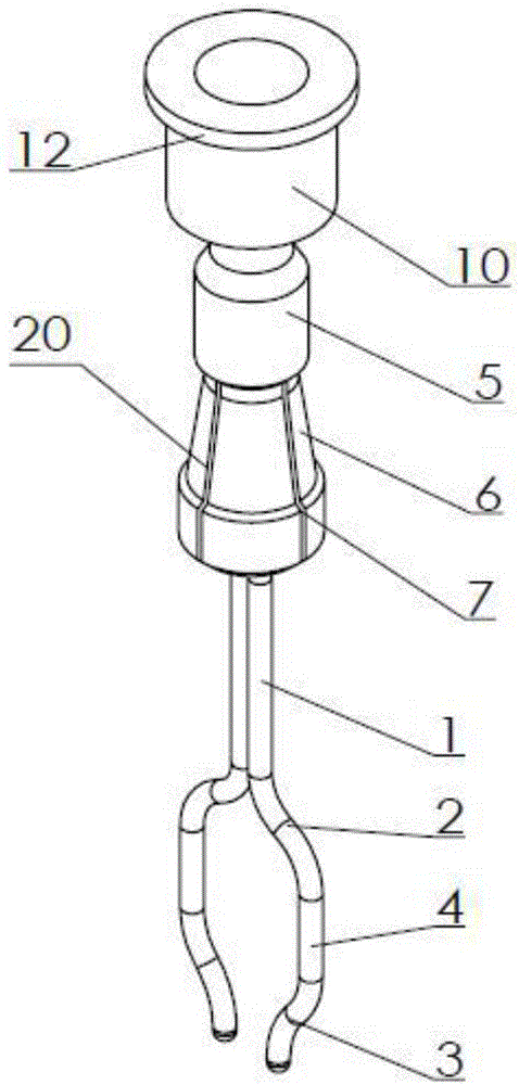
[0013] Examples of the present invention figure 1 , 2 As shown, the powder sleeve chuck includes a chuck and an elastic wire, the elastic wire is one, and the elastic wire is folded in half into a left half and a right half with left and right symmetry, and the upper section 1 of the left half and the right half of the elastic wire is The straight sections close together, the middle section 2 of the left half and the right half gradually bends outward, the lower section 3 of the left half and the right half gradually retracts, and an arc arch is formed at the junction of the lower section and the middle section, and the arc arch can be One end of the arc-shaped vault can also be a straight section. In this embodiment, the connection between the lower section and the middle section is connected by a transition section 4. The transition section is in a vertical state, which can better contact with the inner wall of the bushing, and the connection is more stable. , Elastic threa...


PUM


Abstract

The invention discloses a powder shaft sleeve chuck. The powder shaft sleeve chuck is characterized by comprising an elastic wire left half portion and an elastic wire right half portion which are folded to be in left-and-right symmetry; the upper segment of the elastic wire left half portion and the upper segment of the elastic wire right half portion are straight segments which are in abut joint, the middle segments are gradually bent outwards, the lower segments are gradually and inwards retracted, arches are formed at the connecting positions of the lower segments and the middle segments, the upper segment of the chuck is a threaded connection head connected with a handle threaded connector, the lower segment of the chuck is a cone body with the small upper and the large lower, the cone body is formed in a manner that the connecting position of the threaded connection head extends downwards, a left and right opening which penetrates left and right is formed in the cone body and divides the cone body into paws in front-and-back symmetry, vertical limiting grooves which are in left-and-right centering and are in front-and-back symmetry are formed in the opposite faces of the paws, the upper segments of the elastic wire left half portion and the elastic wire right half portion can be inserted into the position between two vertical limiting grooves in a matched manner, a casing pipe is arranged on the outer side of the cone body, and a cone face abutting against the outer face of the cone body is arranged at the lower end of the casing pipe. Detaching is free, direct contact by the hand is avoided, the shaft sleeve is not likely to make contact with impurities, and the chuck is portable and reliable.

Description

technical field [0001] The invention relates to a tool for picking up a powder metallurgy shaft sleeve, in particular to a chuck for a powder shaft sleeve. Background technique [0002] my country is a big industrial country. With the advancement of science and technology, my country's manufacturing industry is booming, the economy is becoming stronger and stronger, new technologies and materials are constantly emerging, and powder metallurgy materials are one of them. Powder metallurgy can make porous, semi-dense or full-dense parts, such as oil bearing sleeves, which are widely used in various industries without cutting. It has unique chemical composition and mechanical and physical properties. It is a traditional metal processing method. Among them, iron powder is widely used because of its low cost and strong practicability. [0003] During the production and installation of the existing metallurgical powder oil-containing bushing, because the pores are filled with lubr...

Claims


Application Information

Patent Timeline
Patent Type & Authority Applications(China)
IPC IPC(8): B25B9/02
CPCB25B9/02
Inventor 雷明
Owner CHONGQING WANSHENG SHUNDA POWDER METALLURGY
Learn More