
Laser etching method and system for RFID tag antenna

A technology of RFID tags and laser etching methods, which is applied in the field of laser etching methods and systems for RFID tag antennas, can solve the problems of complex manufacturing process, irregular line edges, and low precision, and achieve simple manufacturing process and reduce The effect of high processing temperature and processing accuracy

Active Publication Date: 2017-02-22
深圳华工新能源装备有限公司
View PDF6 Cites 4 Cited by
  • Summary
  • Abstract
  • Description
  • Claims
  • Application Information

AI Technical Summary

Problems solved by technology

At present, as products have higher and higher requirements on the performance and size of RFID electronic tags, the etching of traditional RFID tag antennas mainly adopts corrosion processing, which has irregular edges of etched lines, low precision, and complicated production processes. Wait
Although laser etching technology can avoid this defect, due to the high temperature during laser etching, the upper layer of the RFID tag antenna is coated with aluminum foil, and the lower layer is a plastic layer. When etching the upper layer of aluminum foil coating, the lower plastic layer is due to If the temperature is too high, it will cause melting
Therefore, laser etching technology has not been used in the field of RFID tag antenna etching processing, and the defects caused by corrosion processing have not been well resolved

Method used


Image

  • Laser etching method and system for RFID tag antenna

Examples


Embodiment Construction

[0017] Below in conjunction with accompanying drawing and specific embodiment the present invention is described in further detail:

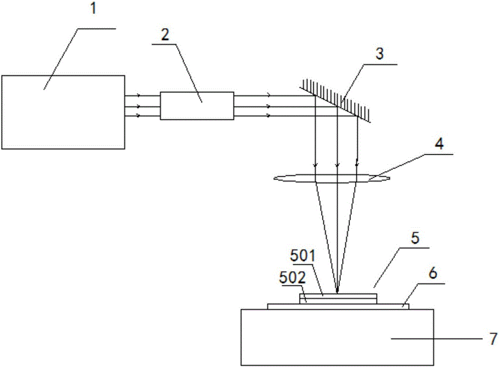
[0018] Such as figure 1 As shown, a laser etching system for an RFID tag antenna includes a laser 1 , a beam expander 2 , a vibrating mirror 3 , a focusing lens 4 , a cooling device 6 and a workbench 7 . In this embodiment, the laser 1 adopts a MOPA fiber laser with a wavelength of 1064nm, a pulse width of 100-200ns, a frequency of 45KHZ, a pulse number of 1500mm / s, and a power of 20w. The zoom factor of the beam expander 2 is 2 times. The focal length of the lens is 160mm, and the format of the focusing lens is 110*110mm, and the cooling device 6 adopts non-woven fabrics that inhale cold water. The focal length of the focusing lens is generally selected as F=160mm, which can increase the power density of the output laser. In practice, select the appropriate lens according to the size of different products. The Gaussian beam from the laser is ...


PUM

PropertyMeasurementUnit
wavelengthaaaaaaaaaa

Abstract

The invention relates to the technical field of laser antenna etching, in particular to a laser etching method for an RFID tag antenna and a system for implementing the method. The system comprises a laser, a beam expanding mirror, a galvanometer, a focusing lens, cooling equipment and a worktable; a tag antenna to be machined is placed on the cooling equipment; a plastic layer at the bottom of the RFID tag antenna to be machined is in close contact with the cooling equipment; the RFID tag antenna to be machined and the cooling equipment are fixed to the worktable together through a clamp; a laser beam which is output by the laser is expanded through the beam expanding mirror, is deflected through the galvanometer, is finally focused through the focusing lens and acts on an aluminium foil plating layer on the upper surface of the tag antenna to be machined. A non-woven fabric water absorbing pad is arranged at the bottom of the RFID tag antenna, so that the machining temperature of the plastic layer is effectively reduced, the plastic layer is prevented from being molten, and a laser etching technology can be applied to the field of RFID tag antennae.

Description

technical field [0001] The invention relates to the technical field of tag antenna etching, in particular to a laser etching method and system for an RFID tag antenna. Background technique [0002] The RFID tag antenna mainly uses a flexible circuit board made of PET film as the base material and composited with aluminum foil. The RFID tag antenna is composed of an upper layer of aluminum foil coating and a lower layer of plastic. RFID tags are mainly used to attach to objects to identify target objects. Currently, they are widely used in industrial automation, mobile commerce, animal husbandry, and anti-counterfeiting identification. At present, as products have higher and higher requirements on the performance and size of RFID electronic tags, the etching of traditional RFID tag antennas mainly adopts corrosion processing, which has irregular edges of etched lines, low precision, and complicated production processes. Wait. Although laser etching technology can avoid this...

Claims


Application Information

Patent Timeline
Patent Type & Authority Applications(China)
IPC IPC(8): B23K26/362B23K26/70B23K26/402
CPCB23K26/36B23K26/402B23K26/703
Inventor 王建刚王雪辉江硕程英张义
Owner 深圳华工新能源装备有限公司
Learn More