Arrangement in a gearbox

A technology for transmission and transmission oil, applied in the direction of gear lubrication/cooling, clutch, belt/chain/gear, etc., can solve the problems of deterioration of lubrication and cooling, increase of fuel consumption, etc. The effect of noise volume

Inactive Publication Date: 2017-02-15
SCANIA CV AB
View PDF4 Cites 0 Cited by
  • Summary
  • Abstract
  • Description
  • Claims
  • Application Information

AI Technical Summary

Problems solved by technology

As a result, the lubrication and cooling of the gears in the gear mesh can deteriorate, and the oil trapped in the gear mesh can lead to higher losses in the gearbox, with consequent increased fuel consumption
There is also an increased risk that oil may be squeezed in the gear mesh as it is difficult for the oil to leave the gear mesh

Method used


Image

  • Arrangement in a gearbox
  • Arrangement in a gearbox
  • Arrangement in a gearbox

Examples


Embodiment Construction

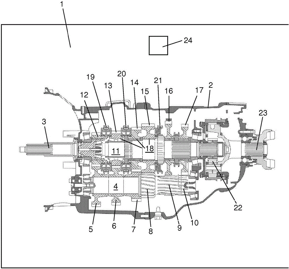
[0016] figure 1 A gearbox is shown, which can be provided in the schematically drawn vehicle 1 . Vehicle 1 may be a heavy goods vehicle. The gearbox is attached inside the housing 2, which contains the gearbox oil. The gearbox includes an input shaft 3 operated by a combustion engine, not shown. The gearbox comprises an intermediate shaft 4 equipped with a number of gears 5-10 of various sizes. The gears 5 - 10 are separate units fixedly fitted on the intermediate shaft 4 or constituting the same part of the intermediate shaft 4 . The gearbox comprises a main shaft 11 equipped with a number of gears 12-17 of various sizes. Each of the gear sets comprises a main gear 5-10 fixedly arranged on the intermediate shaft 4 and a pinion 12-17 rotatably arranged on the main shaft 11 or the input shaft 3 . The transmission is equipped with a release gear which, in a first disengaged state, connects the input shaft 3 via the first gear set 5 , 12 to the side countershaft 4 . In the...


PUM


Abstract

The present invention relates to an arrangement in a gearbox. The gearbox comprises a first shaft (4), a second shaft (3, 11), at least one gear set comprising a primary cogwheel (5-7) arranged on the first shaft (4), and a secondary cogwheel (12-14) arranged on the second shaft (3, 11). The primary cogwheel and the secondary cogwheel have teeth which are engaged in a gear mesh (30-32) with each other. The arrangement comprises a first component (29a-d), which is arranged at a first side of the gear mesh (30-32) between the primary cogwheel (5-7) and the secondary cogwheel (12-14). Said first component (29a-d) comprises a recess (29a2-d2), which is arranged in connection with the gear mesh (30-32), in such a manner that gearbox oil may be led between the first side of the gear mesh (30-32) and the recess (29a2-d2) in said first component (29a-d).

Description

technical field [0001] The invention relates to an arrangement in a gearbox according to the preamble of claim 1 . Background technique [0002] A conventional gearbox includes a countershaft, a mainshaft, several gear sets each including a gear rotatably disposed on the countershaft and a gear disposed on the mainshaft. Synchronizers are used to synchronize and lock the gears on the main shaft in relation to the engaged gear. During operation, transmission oil is directed through the area where the gears of the respective gear sets mesh with each other. As a rule, gears are slanted. The helical teeth create a well-defined oil flow in the gear mesh so that oil is directed from one side of the gear to the other side of the gear. [0003] As a rule, synchronizers are attached to the main shaft connected to the gears on the main shaft. Each synchronizing device may include a displaceably arranged coupling bushing connected to a conical latch having a conical friction surfac...

Claims


Application Information

Patent Timeline
IPC IPC(8): F16H57/04F16D23/06
CPCF16D23/025F16D2300/06F16H57/04F16H57/042F16H57/0427F16H57/12F16H57/0478F16H57/0493F16D2023/0643
Inventor D·黑格斯特伦P·阿内勒夫
Owner SCANIA CV AB
Why Eureka
Try Eureka