
A double-sweep waverider

A waverider and layout technology, which is applied in the field of aerodynamic design of hypersonic vehicles, can solve the problems of poor low-speed performance and poor longitudinal stability of waveriders, and achieve enhanced longitudinal stability, flexible design methods, and improved aerodynamic performance Effect

Active Publication Date: 2019-01-25
CHINA ACAD OF AEROSPACE AERODYNAMICS
View PDF5 Cites 0 Cited by
  • Summary
  • Abstract
  • Description
  • Claims
  • Application Information

AI Technical Summary

Problems solved by technology

[0004] The technical solution of the present invention is to overcome the disadvantages of general waveriders, such as poor low-speed performance and poor longitudinal stability, and to provide a waverider with a double-sweep layout.

Method used


Image

  • A double-sweep waverider
  • A double-sweep waverider
  • A double-sweep waverider

Examples


Embodiment Construction

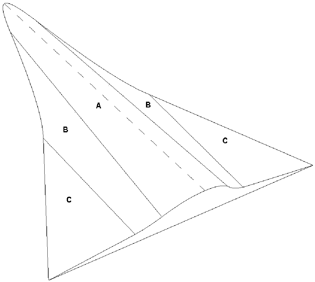
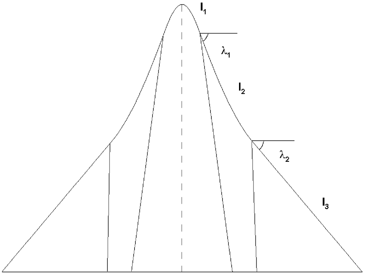
[0026] Design principle of the present invention: separately design the waverider parts with different characteristics, and combine them to obtain the double-sweep characteristic waverider layout form, including the blunt head area, the large-sweep angle area and the small-sweep angle area, such as figure 1 A, B, C areas in. figure 2 The planar shape diagram is given, where l 1 , l 2 , l 3 are the leading edge lines of the above three regions, λ 1 and lambda 2 are the sweep angles of the large and small sweep angle regions, respectively. This shape waverider has advantages in low-speed state performance and longitudinal stability. The blunt region can be obtained by the cone guide or the close cone method, and the other regions are all obtained by the close cone method.

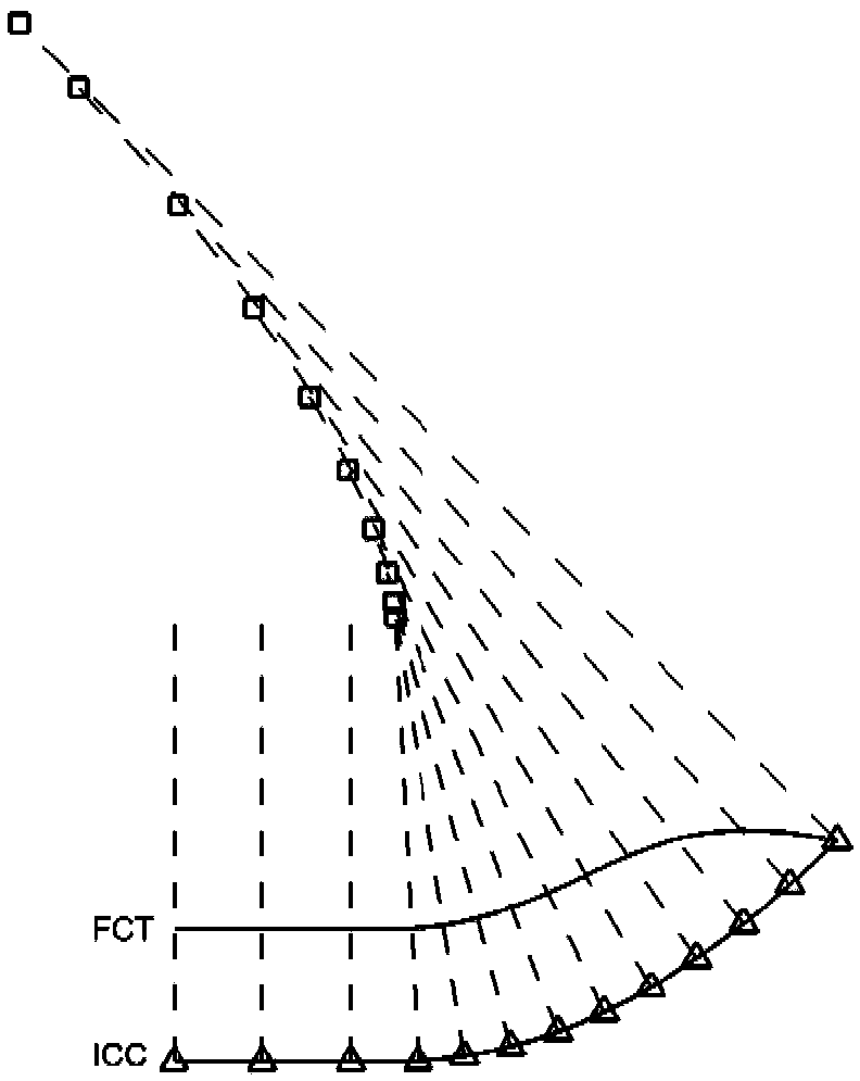
[0027] Briefly introduce the design principle of close cone waveriders, such as image 3 As shown, the ICC curve is used as the exit profile of the shock wave, and a point is drawn on the ICC curve as...


PUM


Abstract

The invention relates to a wave rider of dual sweepback layout. The upper surface of the wave rider is a plane capable of being tracked by a free stream surface, the lower surface of the wave rider is a curved surface with wave rider performance, and the curved surface is described through a blunt end area, large sweepback areas and small sweepback areas. The blunt end area is a streamline tracking curved surface in wave rider design, and the cut rate of a blunt end leading edge line on an axis of symmetry is zero. The large sweepback areas are also called inner wing parts and are smoothly connected to the two sides of the blunt end area, and the outer profile of each large sweepback area is composed of a leading edge line and a curve; each leading edge line is a large sweepback straight line, and the sweepback ranges from 50 degrees to 80 degrees; and the distance between the tail end of each leading edge line and the edge of the blunt end area is smaller than 30% of the half elongation of the wave rider, and each curve is a streamline tracking line in wave rider design. The small sweepback areas are also called outer wing parts and are smoothly connected to the two sides of the streamlines of the large sweepback areas, a leading edge line of each small sweepback area is a straight line, and the sweepback ranges from 30 degrees to 70 degrees.

Description

technical field [0001] The invention relates to the field of aerodynamic design of hypersonic aircraft, especially the layout form of waveriders. Background technique [0002] The high-lift supersonic / hypersonic shape has always been the relentless pursuit of human beings. According to the hyperbolic characteristics of hypersonic inviscid flow, the aerodynamic performance of the aircraft can be improved to a large extent, and the waverider is a typical shape that utilizes this characteristic. The waverider divides the high-pressure aerodynamics on the lower surface of the aircraft by attaching the shock wave to prevent flow leakage, effectively breaking through the lift-drag barrier of the hypersonic aircraft, and has a high lift-to-drag ratio. After decades of development, the waverider has gradually developed from a single configuration in the early stage to a complex configuration with different characteristics, especially the proposal of the close cone method, which can...

Claims


Application Information

Patent Timeline
Patent Type & Authority Patents(China)
IPC IPC(8): B64C21/00
CPCB64C21/00
Inventor 刘传振白鹏
Owner CHINA ACAD OF AEROSPACE AERODYNAMICS
Learn More