
A Shape Optimization Method for 3D Product Model

A product model and optimization method technology, applied in 3D modeling, instrumentation, calculation, etc., can solve the problems of irregular optimization boundary, time-consuming and laborious grid division, and reduced optimization efficiency, so as to reduce design variables, improve calculation efficiency, The effect of convenient interaction

Active Publication Date: 2020-05-05
UNIV OF SHANGHAI FOR SCI & TECH
View PDF7 Cites 0 Cited by
  • Summary
  • Abstract
  • Description
  • Claims
  • Application Information

AI Technical Summary

Problems solved by technology

However, in this method, due to the independent changes of each node, the optimization boundary is often irregular, too many design variables lead to a decrease in optimization efficiency, and continuous data conversion between the design model and the analysis model is required during optimization iterations. Mesh division is time-consuming and laborious

Method used


Image

  • A Shape Optimization Method for 3D Product Model
  • A Shape Optimization Method for 3D Product Model
  • A Shape Optimization Method for 3D Product Model

Examples


experiment example 1

[0076] Experimental example 1: Shape optimization of a ridged cantilever

[0077] The shape optimization method includes the following steps:

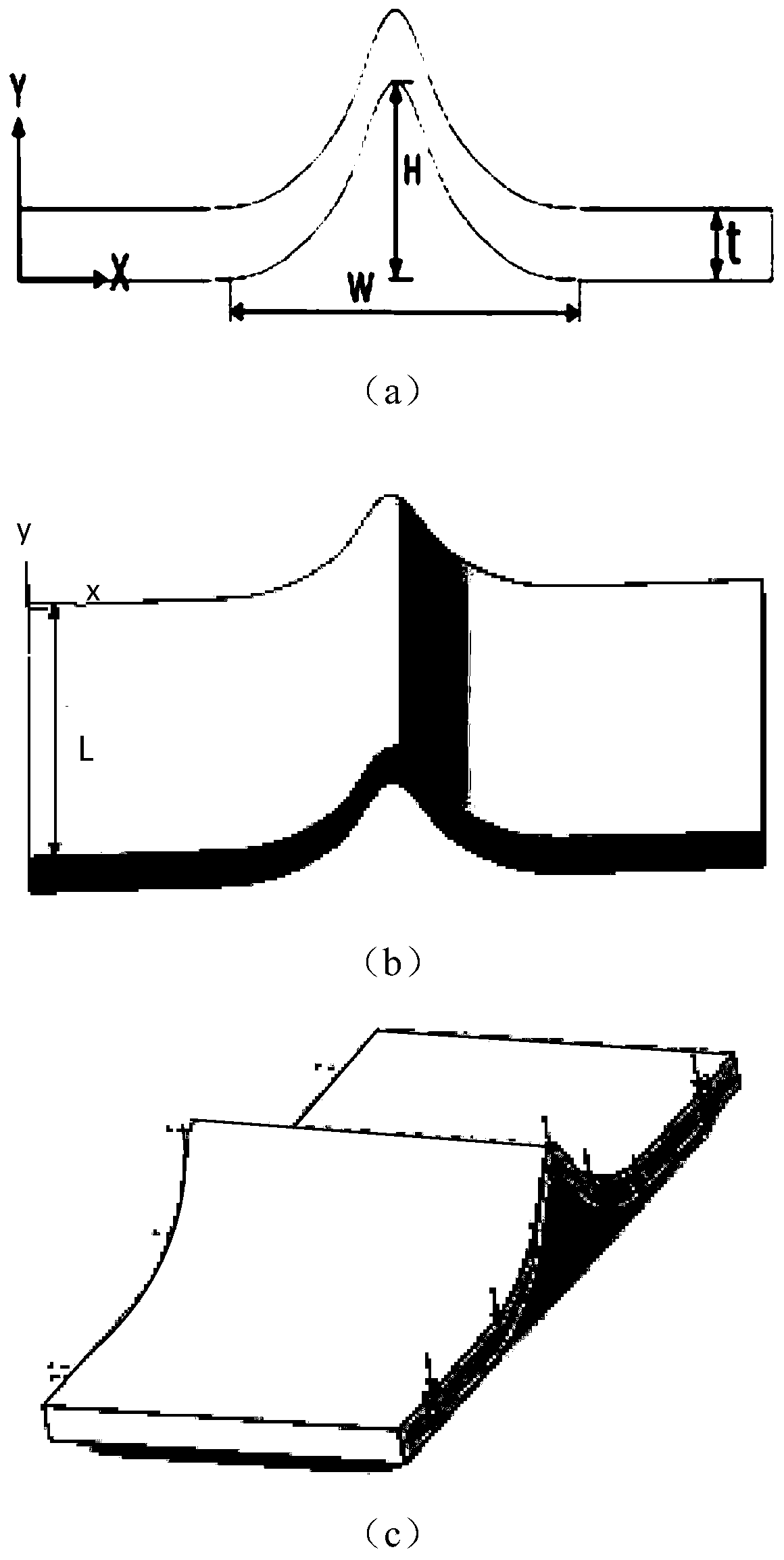
[0078] Step 1. Establish a characteristic frame model of a ridged cantilever beam, such as image 3 (a) and image 3 As shown in (b), the characteristic dimensions of the characteristic frame model include the width W of the ridge, the height H of the ridge, the overall thickness t, and the length L of the ridge, such as image 3 As shown in (c), the load of the model is Z=0, the end face is uniformly pulled along the negative direction of the y-axis, F=-50N, and the boundary condition is that the end face is completely fixed;

[0079] Step 2: Obtain the coordinate matrix of the parameterized control point of the cantilever ridge according to equations (18)~(21):

[0080]

[0081] Where x 0 Is the x coordinate of the ridge vertex, x 1 Is the x coordinate of the control point on the ridge, x 1 ′ Is the updated x 1 , W 0 Is the vertex ridge width...

experiment example 2

[0099] Experimental example 2: The shape optimization method of the dredging cutter arm

[0100] Step 1. Establish the characteristic frame model of the dredging cutter arm, such as Figure 5 As shown, the characteristic dimensions of the characteristic frame model include the axial width bW and the axial length bL of the lower bottom surface of the reamer arm, the axial width tW and the axial length tL of the upper top surface, the height of the reamer arm H, and the load and boundary conditions are : The upper and lower bottom surfaces of the reamer arm are fixedly restrained, and a concentrated force is applied at the designated control point.

[0101] Step 2. When the feature size type is length, the mapping function is derived. Let any two points in the space be (x 0 ,y 0 ,z 0 ) And (x 1 ,y 1 ,z 1 ), the feature size along the X-axis, Y-axis, and Z-axis is determined by W 0 ,L 0 ,H 0 Change to W, L, H, change (x 0 ,y 0 ,z 0 ) As a fixed point, set a moving point (x 1 ,y 1 ,z 1...


PUM


Abstract

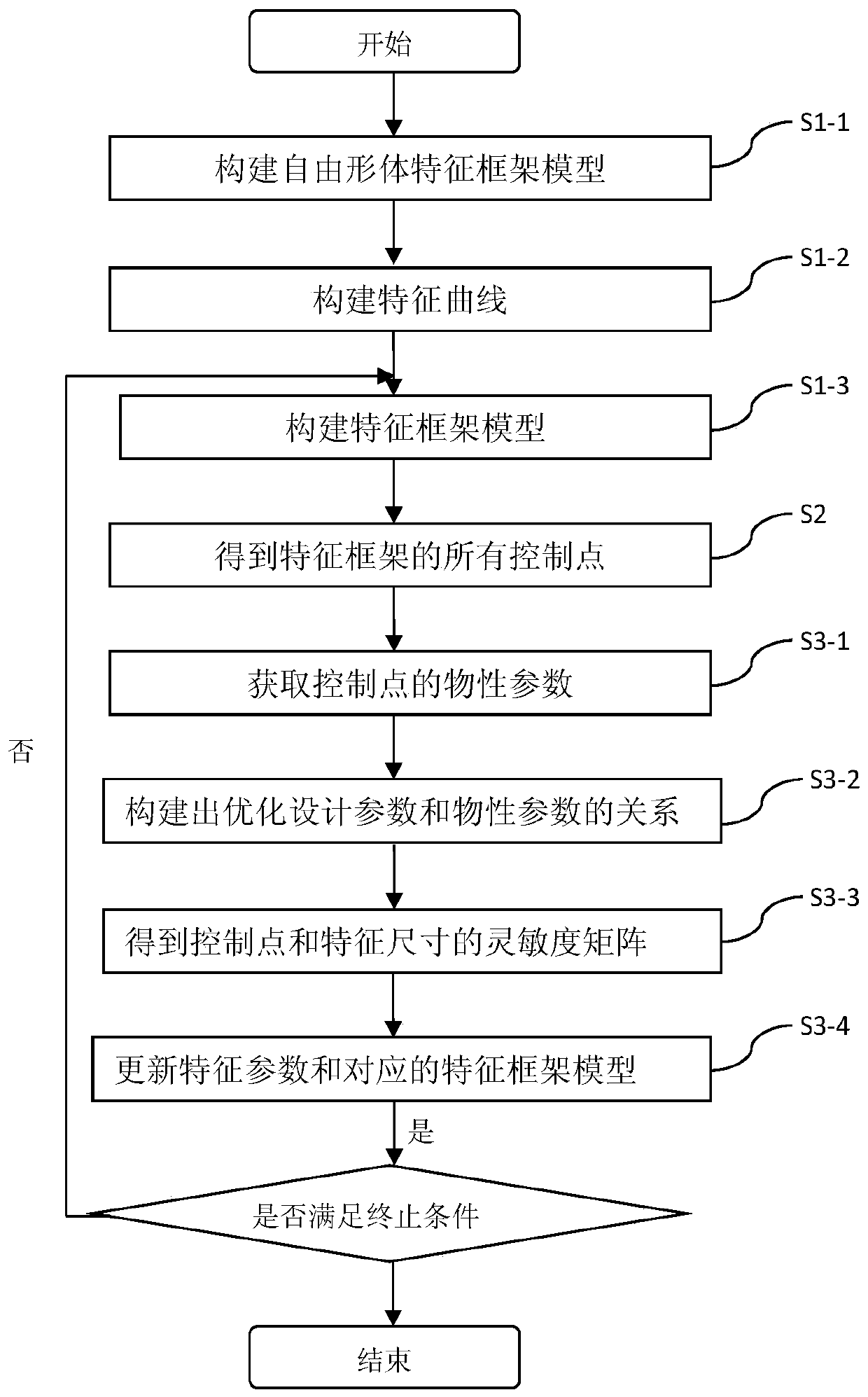
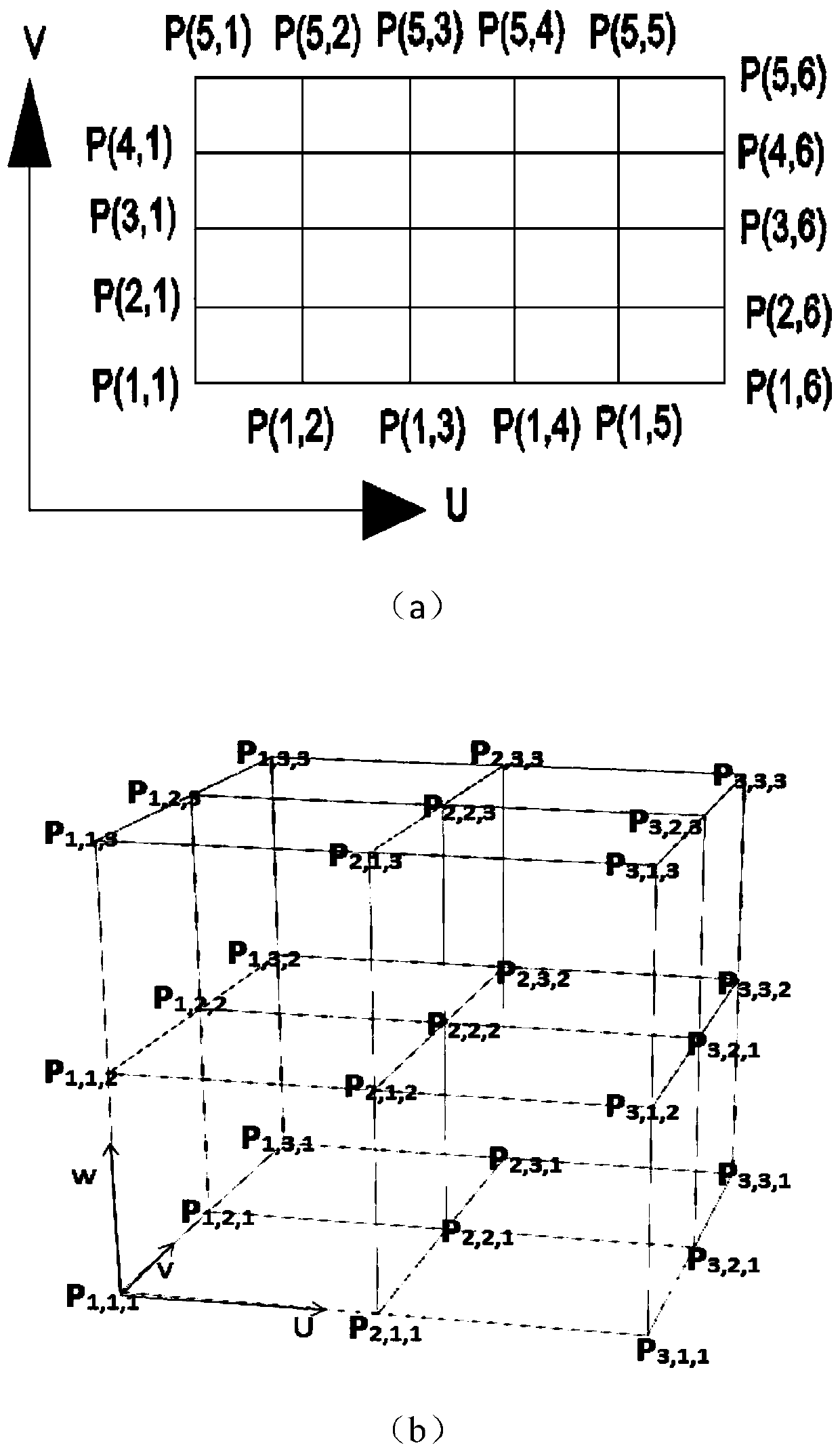
The invention provides a shape optimization algorithm for a three-dimensional product model, and the method comprises the following steps: firstly constructing a product model which is a feature frame model comprising point, line and surface features through employing a reverse solving method or a size measurement method; adding the constraint between the feature elements, and constructing a parameterized feature frame; employing a multi-drive mode, maintaining the constraint between the features, and achieving the modification of the feature frame model; employing a volume parameterization theory for the feature frame to obtain a volume parameterization model which can be used for geometrical analysis; enabling the feature size of the feature frame to serve as the product size or a shape optimization parameter, deducing the physical performances of a product and the sensitivity matrix of the design parameters, and optimizing the parameters, so as to achieve the optimized design of a product model.

Description

Technical field [0001] The invention belongs to the field of three-dimensional product model shape optimization design, and mainly relates to a shape optimization method based on a product model feature frame. Background technique [0002] In traditional shape optimization, the nodes of finite elements are usually used as design variables. However, in this method, due to the independent changes of each node, the optimization boundary is often irregular, and the optimization efficiency is reduced due to too many design variables. The design model and the analysis model require continuous data conversion during the optimization iteration. Meshing is time-consuming and labor-intensive. These shortcomings are caused by the different mathematical languages ​​used in the design model and the analysis model, that is, the spline basis function is used in the geometric modeling, and the Lagrange basis function or Hermitian polynomial is used in the analysis model. Summary of the inventi...

Claims


Application Information

Patent Timeline
Patent Type & Authority Patents(China)
IPC IPC(8): G06T17/00G06T19/00
CPCG06T17/00G06T19/00
Inventor 陈龙张高朋
Owner UNIV OF SHANGHAI FOR SCI & TECH
Learn More