
A method for monitoring the working state of the iron core inside the box based on magnetic flux leakage

A technology of working state and iron core, which is applied in the field of monitoring the working state of the iron core inside the box based on magnetic flux leakage, can solve the problems of interference transmission accuracy, influence on reliability, misoperation of relay protection devices, etc., and achieve the goal of avoiding the influence of distortion Effect

Active Publication Date: 2018-11-16
卢庆港
View PDF9 Cites 0 Cited by
  • Summary
  • Abstract
  • Description
  • Claims
  • Application Information

AI Technical Summary

Problems solved by technology

[0003] With the continuous increase of transformer capacity and limited transportation, the volume and shape design are greatly restricted, and the problem of magnetic flux leakage of transformers is becoming more and more serious. The steady-state leakage flux of transformers in normal operation leads to the increase of local iron loss on the tank wall. The local temperature rise is too high, which can be detected and verified through the overcurrent test and solved by magnetic shielding. However, no effective measures have been taken to shield the transient leakage flux when the core is transiently saturated due to the excitation inrush current. Leakage flux interferes with the transmission accuracy of bushing CT, which may easily lead to misoperation of relay protection devices and affect the reliability of operation

Method used


Image

  • A method for monitoring the working state of the iron core inside the box based on magnetic flux leakage
  • A method for monitoring the working state of the iron core inside the box based on magnetic flux leakage
  • A method for monitoring the working state of the iron core inside the box based on magnetic flux leakage

Examples


Embodiment Construction

[0026] The preferred embodiments of the present invention are given below in conjunction with the accompanying drawings, and a single-phase dual-winding transformer is specifically used to illustrate the specific application of the present invention.

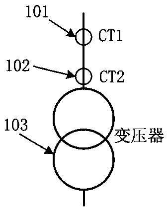
[0027] In the power system, for large-capacity transformers, based on transportation and manufacturing factors, three independent single-phase transformers are usually combined to form a three-phase transformer after installation. The common connection methods of single-phase transformers and the power grid are as follows: figure 1 As shown, two sets of CTs are configured. The line CT 101 is installed near the circuit breaker of the transformer lead, and the transformer bushing CT 102 is installed inside the elevated base above the transformer body, near the windings and cores inside the transformer.

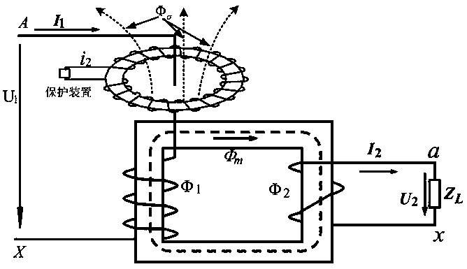
[0028] The internal magnetic flux of the single-phase transformer and the leakage magnetic flux in the bushing area such as figure 2 A...


PUM


Abstract

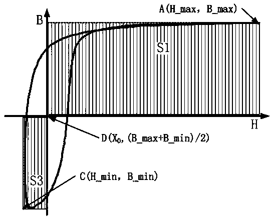
The invention provides a method for monitoring the working state of the iron core inside the box based on magnetic flux leakage. Through the monitoring of magnetic flux leakage, the working state of the iron core is indirectly obtained, and whether the iron core is saturated is judged. In the same current loop outside the box with the iron core and the winding inside Two sets of CTs are installed in different spatial positions, and the secondary current and loop voltage of these two sets of CTs are used without additional hardware. The BH curve representing the change of the core magnetic flux can be reconstructed by using software to process the voltage and current data in real time. According to the BH The characteristics of the curve monitor the working state of the iron core and are used as the action criterion of the relay protection device. The present invention can use the quantified asymmetry of the iron core state as real-time data to draw a change curve on the monitoring screen, and at the same time, by setting the alarm threshold, an automatic alarm is realized when an abnormal state of the iron core is detected; Install any magnetic field measurement probes in the area to avoid the distortion effect of the probes and lead wires on the local high-voltage electric field, and have no impact on the reliability of the equipment.

Description

Technical field [0001] The invention belongs to the technical field of power system automation, and specifically relates to a method for monitoring the working state of an iron core inside a cabinet based on magnetic flux leakage. Background technique [0002] When the windings in the transformer are connected to the power supply, magnetic flux will be generated in the iron core. The magnetic flux generated in the iron core due to the excitation voltage is called the main magnetic flux. The size of the main magnetic flux is determined by the size of the excitation voltage. It is generated when the rated voltage is excited. The main magnetic flux should not saturate the core, that is, the magnetic flux density should not be saturated at this time. The main magnetic flux forms a closed loop in the core of the closed magnetic circuit, but will overflow the core after the core is saturated. The part of the magnetic flux that has not been closed by the core is leakage flux. The leakag...

Claims


Application Information

Patent Timeline
Patent Type & Authority Patents(China)
IPC IPC(8): G01R33/12
CPCG01R33/12
Inventor 乐晓蓉卢庆港
Owner 卢庆港
Learn More