
A light-emitting diode chip and its preparation method

A light-emitting diode and chip technology, applied in semiconductor devices, electrical components, circuits, etc., can solve the problems of small number of chips and sacrifice of light-emitting area area, etc., and achieve the effect of increasing the number of chips, reducing the surface area, and saving the occupied area

Active Publication Date: 2019-08-02
HC SEMITEK ZHEJIANG CO LTD
View PDF7 Cites 0 Cited by
  • Summary
  • Abstract
  • Description
  • Claims
  • Application Information

AI Technical Summary

Problems solved by technology

[0005] The insulating medium on the side wall of the stepped structure can effectively avoid the short circuit between the n-type layer and the p-type layer, but limited by the photolithography process and the scribing process, the stepped structure set in the edge region of the LED chip has a certain width , sacrificing a certain light-emitting area, resulting in a small number of chips produced by a single wafer (wafer)

Method used


Image

  • A light-emitting diode chip and its preparation method
  • A light-emitting diode chip and its preparation method
  • A light-emitting diode chip and its preparation method

Examples


Embodiment 1

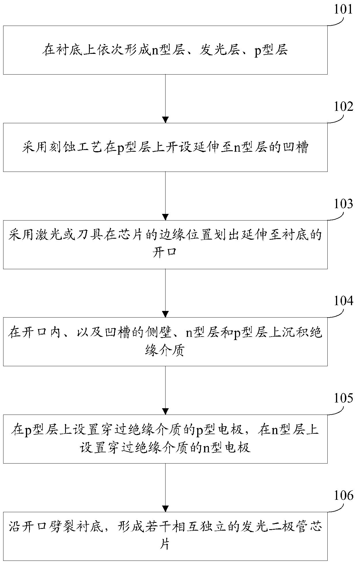
[0034] The embodiment of the present invention provides a method for preparing a light-emitting diode chip, see figure 1 , the preparation method comprises:

[0035] Step 101: sequentially forming an n-type layer, a light-emitting layer, and a p-type layer on a substrate.

[0036] In this embodiment, the substrate can be a sapphire substrate, the n-type layer can be an n-type GaN layer, the light-emitting layer can include alternately stacked InGaN quantum well layers and GaN quantum barrier layers, and the p-type layer can be a p-type GaN layer .

[0037] Step 102: using an etching process to open a groove extending to the n-type layer on the p-type layer.

[0038] Step 103: Using a laser or a cutter to mark an opening extending to the substrate at the edge of the chip.

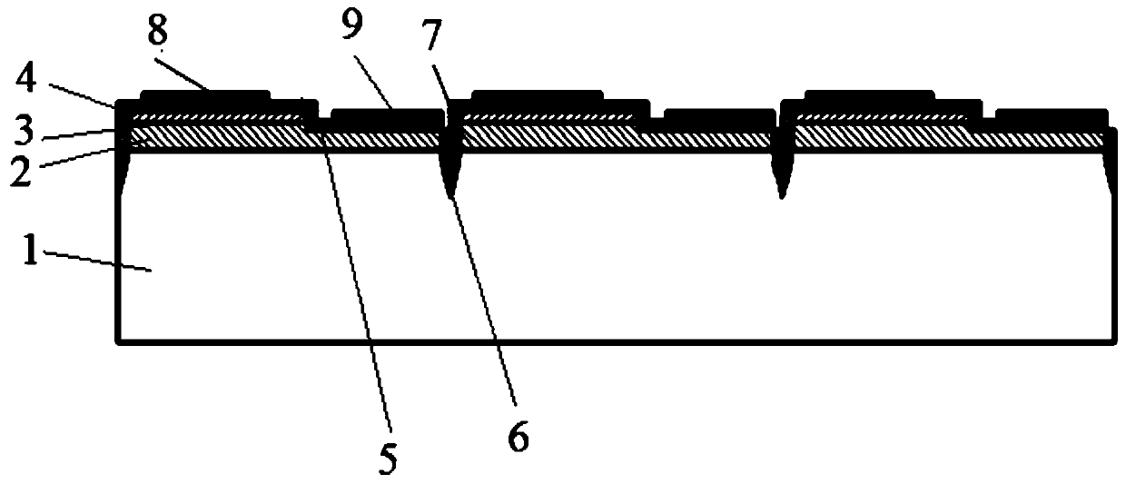
[0039] Figure 2a It is a schematic structural diagram of the light emitting diode chip after step 103 is performed. Wherein, 1 is a substrate, 2 is an n-type layer, 3 is a light-emitting layer, 4 is a ...

Embodiment 2

[0068] The embodiment of the present invention provides a light-emitting diode chip, which can be prepared by the preparation method provided in Embodiment 1, see image 3 with Figure 4 The light-emitting diode chip includes a substrate 1, and an n-type layer 2, a light-emitting layer 3, and a p-type layer 4 sequentially stacked on the substrate 1, and a groove 5 extending to the n-type layer 2 is opened on the p-type layer 4 The edge position of the LED chip is provided with an opening 6 extending to the substrate 1, an insulating medium 7 is deposited in the opening 6, on the sidewall of the groove 5, on the n-type layer 2 and the p-type layer 4, and the p-type electrode 8 is set on the p-type layer 4 through the insulating medium 7, and the n-type electrode 9 is set on the n-type layer 2 through the insulating medium 7.

[0069] In the embodiment of the present invention, an opening extending to the substrate is provided at the edge of the light-emitting diode chip, and a...


PUM


Abstract

The invention discloses a light-emitting diode chip and a preparation method thereof, and belongs to the technical field of semiconductors. The preparation method comprises the steps of sequentially forming an n-type layer, a light-emitting layer and a p-type layer on a substrate; forming a groove which extends to the n-type layer in the p-type layer by adopting an etching process; cutting an opening which extends to the substrate at the edge position of a chip by adopting laser light or a tool; depositing an insulating medium in the opening, on the side wall of the groove and on the n-type layer and the p-type layer; arranging a p-type electrode which passes through the insulating medium on the p-type layer; arranging an n-type electrode which passes through the insulating medium on the n-type layer; and splitting the substrate along the opening and forming a plurality of independent light-emitting diode chips. According to the light-emitting diode chip, the condition that the groove is also arranged in the edge region of the chip is avoided, the edge of a light-emitting region is the edge of the chip; the area occupied by the chip is significantly reduced; the side surface of the chip is protected as before; and the reliability of the chip is not affected.

Description

technical field [0001] The invention relates to the technical field of semiconductors, in particular to a light emitting diode and a preparation method thereof. Background technique [0002] Light Emitting Diode (English: Light Emitting Diode, referred to as LED) is a semiconductor diode that can convert electrical energy into light energy. [0003] LED chip is the core component of LED. At present, the LED chip includes a sapphire substrate, and an n-type layer, a light-emitting layer, and a p-type layer stacked on the sapphire substrate in sequence. The step structure of the step structure, the side wall of the step structure, the n-type layer and the p-type layer are all provided with an insulating medium, the n-type electrode is set on the n-type layer through the insulating medium, and the p-type electrode is set on the p-type layer through the insulating medium. type layer. [0004] In the process of realizing the present invention, the inventor finds that there are...

Claims


Application Information

Patent Timeline
Patent Type & Authority Patents(China)
IPC IPC(8): H01L33/00H01L33/44
CPCH01L33/0095H01L33/44
Inventor 罗红波
Owner HC SEMITEK ZHEJIANG CO LTD
Learn More