Battery steel belt, battery steel shell using steel belt and manufacturing method for steel shell

A battery steel case and steel strip technology, applied to battery components, circuits, electrical components, etc., can solve the problems of false battery power, rust on the outer surface of the battery, and increased cost of the steel case, and achieve the effect of reducing waste

Active Publication Date: 2017-02-01
宁波堇山新材料有限公司
View PDF16 Cites 0 Cited by
  • Summary
  • Abstract
  • Description
  • Claims
  • Application Information

AI Technical Summary

Problems solved by technology

[0007] (1) High material cost
When the steel strip is stretched and punched into a steel shell, more than 30% of scraps will be produced, and the nickel in the pre-nickeled steel strip is uniformly plated on the steel strip, so the waste of nickel plated on the scraps makes the steel shell Increased costs, resulting in higher production costs for the pre-nickel plating process than the post-nickel plating process;
[0008] (2) Alkaline batteries are prone to leakage when using this process for long-term storage
The nickel layer on the surface of the pre-nickel-plated steel strip is also continuously stretched and deformed during the stretching and punching process of the steel shell, and cracks will appear in the coating layer, and the original cracks and other defective points will continue to be stretched and expanded, forming a large number of through holes. The cracks in the Fe matrix, the iron components on the Fe matrix under these cracks will gradually dissolve during the long-term storage of the battery, causing battery leakage and affecting the storage life of the battery;
[0009] (3) The cracks through the matrix produced by the steel shell during the stretching and punching process are likely to cause rust on the outer surface of the battery
[0013] (2) Limited by the deep hole electroplating process, the deposition rate of the coating on the outer surface of the steel shell is much greater than that on the inner surface. In order to increase the thickness of the coating on the inner surface as much as possible, the thickness of the coating on the outer surface must be increased synchronously, resulting in The thickness of the coating on the outer surface of the steel shell is much higher than the thickness required for normal anti-corrosion outside the steel shell, resulting in the waste of high-priced nickel metal and the increase of electroplating costs
For example, for the LR6 steel shell, when the thickness of the bottom coating on the inner surface reaches 0.25 microns, the thickness of the coating on the outer surface of the head of the steel shell reaches an average of more than 3.5 microns, and the thickest part even exceeds 5 microns, while the thickness of the nickel coating on the outer surface The main function is to prevent rust, usually 2 microns is enough, which causes a waste of nickel on the outer surface and increases the cost of electroplating;
[0014] (3) Although the nickel coating in the post-plating process no longer needs to be stretched, and there is no problem of cracks in the coating during the stretching process. Theoretically speaking, the compactness of the electroplating layer is relatively good, but because deep hole electroplating requires a large amount of electroplating Additives, as well as the impact of additives on the coating due to the continuous decomposition of additives during the electroplating process, electroplating process and production process management will seriously affect the quality of the coating. Cause problems such as a substantial increase in the porosity of the coating. In severe cases, the porosity will be higher than that of the steel shell produced by the pre-nickeling process, and the storage life of the battery will even be lower than that of the pre-nickeling process;
[0015] (4) There is a certain amount of sulfur in the coating of the post-electroplating process, which is the product of the decomposition of electroplating additives. The existence of sulfur in the coating will affect the corrosion resistance of the coating, and the surface of the coating will gradually fade within a few months. Yellowing and oxidation will also affect the surface conductivity and cause false power shortages when the battery is in use;
[0016] (5) The post-plating process tends to produce a large number of nickel flowers at the incision of the steel shell. These nickel flowers are easy to peel off into nickel powder during battery production, and are easily mixed into the battery to cause battery leakage
[0017] There is still a practical problem in the post-plating process: with the strengthening of the government's environmental protection efforts, scattered steel shell electroplating manufacturers are increasingly feeling the pressure of environmental protection. The cost of electroplating is mainly due to the increasing cost of environmental protection. Productivity means lower cost of electroplating

Method used


Image

  • Battery steel belt, battery steel shell using steel belt and manufacturing method for steel shell
  • Battery steel belt, battery steel shell using steel belt and manufacturing method for steel shell
  • Battery steel belt, battery steel shell using steel belt and manufacturing method for steel shell

Examples


Embodiment 1

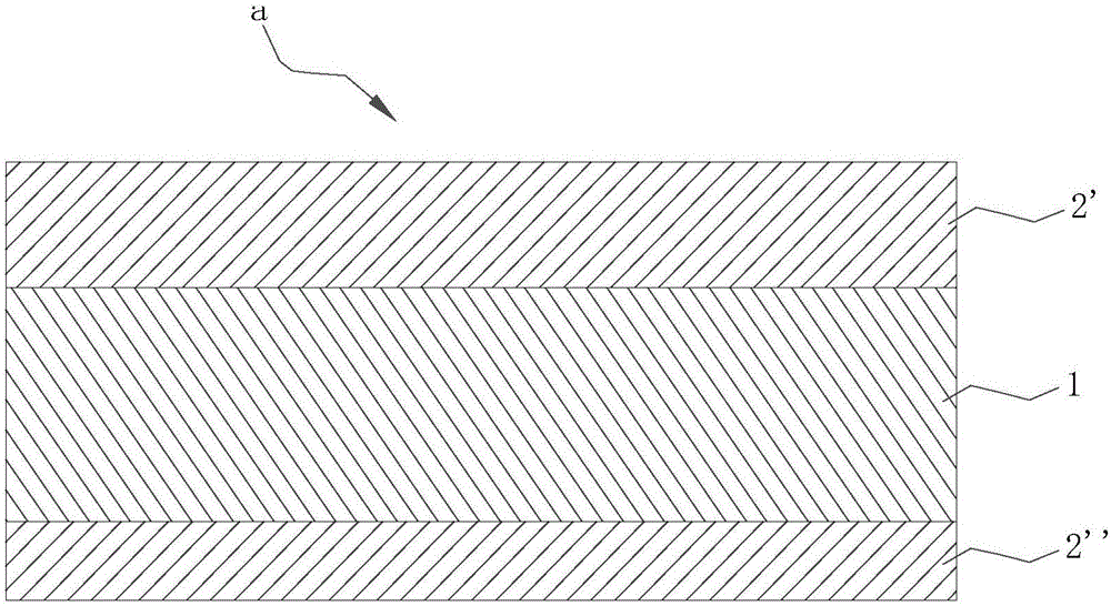
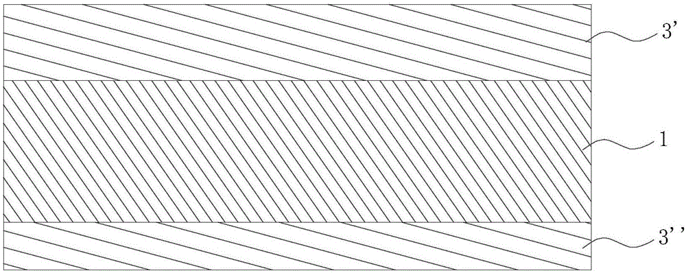
[0051] like figure 1 As shown, the battery steel strip a of this embodiment includes a Fe matrix 1 and an Fe-Ni alloy layer, and Fe-Ni alloy layers 2' and 2" are formed on two surfaces of the Fe matrix 1 respectively. The thickness of the Fe-Ni alloy layer 2 ′ on the surface is 0.4 μm, and the thickness of the Fe-Ni alloy layer 2 ″ on the outer surface of the Fe matrix 1 is 0.1 μm. The above-mentioned Fe-Ni alloy layer is obtained by alloying the Fe matrix 1 and the Ni-plated layer on the surface thereof through heat treatment, that is, as figure 2 As shown in the figure, Ni plating layers 3', 3" are formed on the two surfaces of the Fe matrix 1 first, and then the Ni plating layers 3', 3" are interpenetrated and alloyed with the Fe matrix 1 through heat treatment to form Fe-Ni layers. Alloy layers 2', 2". Different from the conventional Fe-Ni electroplating layer formed directly by electroplating, the Fe-Ni alloy layer formed by heat treatment in the present invention has s...

Embodiment 2

[0063] like figure 1 As shown, the battery steel strip a of this embodiment includes a Fe matrix 1 and Fe-Ni alloy layers 2', 2", and Fe-Ni alloy layers 2', 2" are formed on two surfaces of the Fe matrix 1, respectively, wherein , the thickness of the Fe-Ni alloy layer 2' on the inner surface of the Fe matrix 1 is 0.5 μm, and the thickness of the Fe-Ni alloy layer 2” on the outer surface of the Fe matrix 1 is 0.25 μm. The Fe matrix 1 and the Ni-plated layers 3', 3" on its surface are obtained by alloying by heat treatment, that is, as figure 2 As shown, the surface of Fe substrate 1 is firstly plated with Ni to form Ni plating layers 3', 3", and then the Ni plating layers 3', 3" are alloyed with Fe substrate 1 through heat treatment to form Fe-Ni alloy layers 2', 3", 2". Different from the Fe-Ni electroplating layer directly formed by electroplating in the prior art, the Fe-Ni alloy layers 2', 2" formed by heat treatment in the present invention have stronger bonding force w...

Embodiment 3

[0075] like figure 1 As shown, the battery steel strip a of this embodiment includes a Fe matrix 1 and Fe-Ni alloy layers 2', 2", and Fe-Ni alloy layers 2', 2" are formed on two surfaces of the Fe matrix 1, respectively, wherein , the thickness of the Fe-Ni alloy layer 2' on the inner surface of the Fe matrix 1 is 0.7 μm, and the thickness of the Fe-Ni alloy layer 2” on the outer surface of the Fe matrix 1 is 0.2 μm. The Fe matrix 1 and the Ni-plated layers 3', 3" on its surface are obtained by alloying by heat treatment, that is, as figure 2 As shown, the surface of Fe substrate 1 is firstly plated with Ni to form Ni plating layers 3', 3", and then the Ni plating layers 3', 3" are alloyed with Fe substrate 1 through heat treatment to form Fe-Ni alloy layers 2', 3", 2". Different from the Fe-Ni electroplating layer directly formed by electroplating in the prior art, the Fe-Ni alloy layers 2', 2" formed by heat treatment in the present invention have stronger bonding force wi...


PUM

PropertyMeasurementUnit
thicknessaaaaaaaaaa
thicknessaaaaaaaaaa
thicknessaaaaaaaaaa

Abstract

The invention relates to a battery steel belt, a battery steel shell using the steel belt and a manufacturing method for the steel shell. The battery steel belt is characterized in that nickel electroplated layers are separately formed on the surfaces, wherein the thickness of the nickel plated layer on the inner surface is greater than that of the nickel plated layer on the outer surface; the plated layers on the surfaces of the steel belt are subjected to thermal treatment to interpenetrate with matrix to form Fe-Ni alloy layers; and the Fe-Ni alloy layers formed by thermal treatment are compact in structure, are good in corrosion resistance; bonding force between the Fe-Ni alloy layers and Fe matrix is much greater than that between regular electroplated layers and the Fe matrix, so that the possibility of generating cracks during steel shell punching is reduced, and conditions can be provided for forming post-electroplated Ni layers with good bonding force on surfaces. After being subjected to nickel pre-plating and nickel post-plating, the steel shell has the characteristic that the nickel layer on the inner surface is thick, so that power storage of a battery is improved, compactness and corrosion resistance of the battery are much better than those of a battery with a single electroplated nickel layer, and therefore, the battery leakage problem caused by dissolution of steel shell matrix iron during long-term storage of the battery is solved.

Description

technical field [0001] The invention relates to the technical field of battery steel strips and steel shells, in particular to a battery steel strip, a battery steel shell using the steel strip, and a preparation method of the steel shell. Background technique [0002] The steel shell for the battery adopts the process of nickel plating on the surface of the iron substrate to prevent corrosion, and the nickel plating process is usually divided into two processes: pre-nickel plating and post-nickel plating. [0003] Foreign battery manufacturers mainly use the pre-nickel plating process. In this process, nickel is first plated on the surface of the raw material of the steel shell, the steel strip substrate, to become a pre-nickel-plated steel strip, and then stretched and punched into a steel shell. The pre-nickel plating process has the following advantages: [0004] (1) Since the pre-nickel plating process is to first electroplate nickel on the surface of the raw steel st...

Claims


Application Information

Patent Timeline
Patent Type & Authority Applications(China)
IPC IPC(8): C25D7/06C25D5/50C25D5/14H01M2/02H01M50/124
CPCC25D5/14C25D5/50C25D7/0614H01M50/124Y02E60/10
Inventor 忻锋光
Owner 宁波堇山新材料有限公司
Why Eureka
Try Eureka