Dechlorination method for chlorine-containing plastic
A dechlorination and plastic technology, applied in the chemical industry, can solve secondary pollution and other problems, and achieve the effect of no secondary pollution, considerable economic benefits, and high economic value
- Summary
- Abstract
- Description
- Claims
- Application Information
AI Technical Summary
Problems solved by technology
Method used
Image
Examples
Embodiment 1
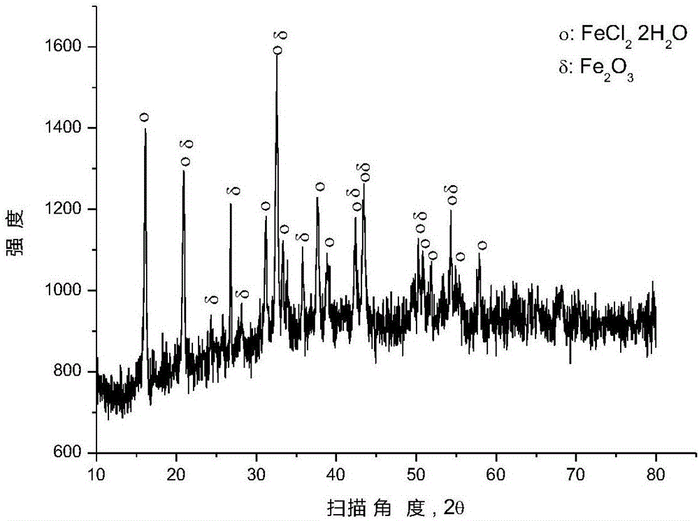
[0035]After mixing ferric oxide and polyvinyl chloride (number average molecular weight: 6500) according to the molar ratio of ferric oxide and chlorine in polyvinyl chloride (1:2), place it in a closed reaction kettle under the protection of argon for 250 ℃ for 0.5 hour, and the pressure in the reaction kettle is 1 to 5 atmospheres during the reaction. After the reaction, the reactor was opened to reclaim the gaseous hydrocarbons, and an appropriate amount of solid phase substances were taken from the reaction liquid in the reactor for XRD analysis, and the results were as follows: figure 1 as shown, figure 1 It is the XRD figure of the solid phase material provided by Example 1 of the present invention. pass figure 1 It can be seen that after the pyrolysis reaction, most of the iron oxide has been converted into ferrous chloride, and some iron oxide remains unreacted.
[0036] In order to separate the chlorine salt in the reaction solution in the still, the reaction solut...
Embodiment 2
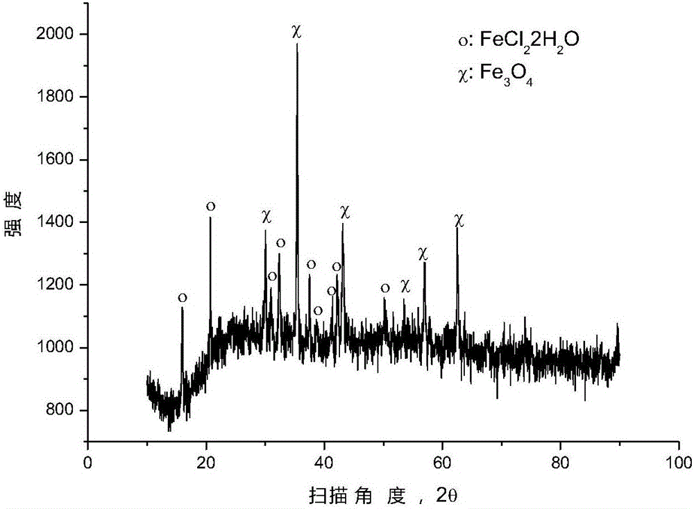
[0038] After mixing ferric oxide and polyvinyl chloride (number average molecular weight: 6500) according to the molar ratio of ferric oxide and chlorine in polyvinyl chloride (1:3), place it in a closed reaction kettle under the protection of argon for 250 ℃ for 0.5 hour, and the pressure in the reaction kettle is 1 to 5 atmospheres during the reaction. After the reaction, the reactor was opened to reclaim the gaseous hydrocarbons, and an appropriate amount of solid phase substances were taken from the reaction liquid in the reactor for XRD analysis, and the results were as follows: figure 2 as shown, figure 2 It is the XRD pattern of the solid phase substance provided by Example 2 of the present invention. pass figure 2 It can be seen that after the pyrolysis reaction, most of the ferric oxide has been converted into ferrous chloride, and some ferric oxide remains unreacted.
[0039] In order to separate the chlorine salt in the reaction solution in the still, the reac...
Embodiment 3
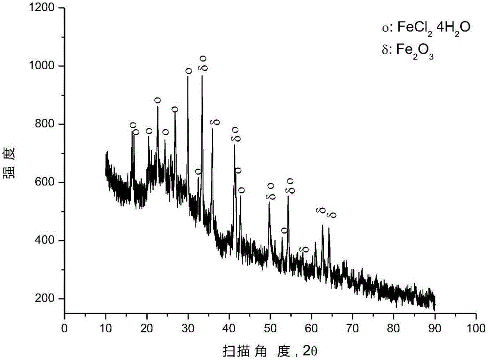
[0041] After mixing the mixture of hematite and 90wt% polyvinyl chloride (number average molecular weight: 6500) + 5wt% polyethylene + 5wt% polypropylene according to the molar ratio of ferric oxide and chlorine in polyvinyl chloride (1:2) , placed in a closed reactor at 377° C. for 0.5 hour reaction under argon protection, and the pressure in the reactor was 1 to 5 atmospheres during the reaction. After the reaction is over, the reactor is opened to recover gaseous hydrocarbons, and an appropriate amount of solid phase substances are taken from the reaction liquid in the reactor for XRD analysis, and the results are as follows: image 3 as shown, image 3 It is the XRD pattern of the solid phase material provided by Example 3 of the present invention. pass image 3 It can be seen that after the pyrolysis reaction, most of the iron oxide has been converted into ferrous chloride, and some iron oxide remains unreacted.
[0042] In order to separate the chlorine salt in the re...
PUM
 Abstract
Description
Claims
Application Information
 - R&D
- Intellectual Property
- Life Sciences
- Materials
- Tech Scout
- Unparalleled Data Quality
- Higher Quality Content
- 60% Fewer Hallucinations
Browse by: Latest US Patents, China's latest patents, Technical Efficacy Thesaurus, Application Domain, Technology Topic, Popular Technical Reports.
© 2025 PatSnap. All rights reserved.Legal|Privacy policy|Modern Slavery Act Transparency Statement|Sitemap|About US| Contact US: help@patsnap.com


