


Quick Research
Generate reliable direction feasibility study reports for your R&D in just a few steps.

Technical Q&A
Discover and master advanced knowledge NOW. Basics, ideas, possibilities, all at once.

Find Solutions
As an expert in R&D theories, this can generate solutions to your technical problems instantly.

Evaluate Feasibility
Analyze your overall solution with one click, know your potential R&D risks in advance.

Monitor Landscape
Get weekly tech updates, stay abreast of the latest tech innovations and key insights.
Composite type heat dissipation structure
A heat dissipation structure and composite technology, applied in the direction of cooling/ventilation/heating transformation, etc., can solve the problems of flat cooling fins, reduced heat dissipation efficiency, poor thermal conductivity, etc.
- Summary
- Abstract
- Description
- Claims
- Application Information
AI Technical Summary
Problems solved by technology
Method used
Image

Examples
no. 1 example 〕
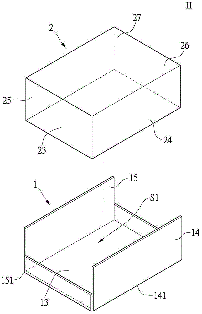
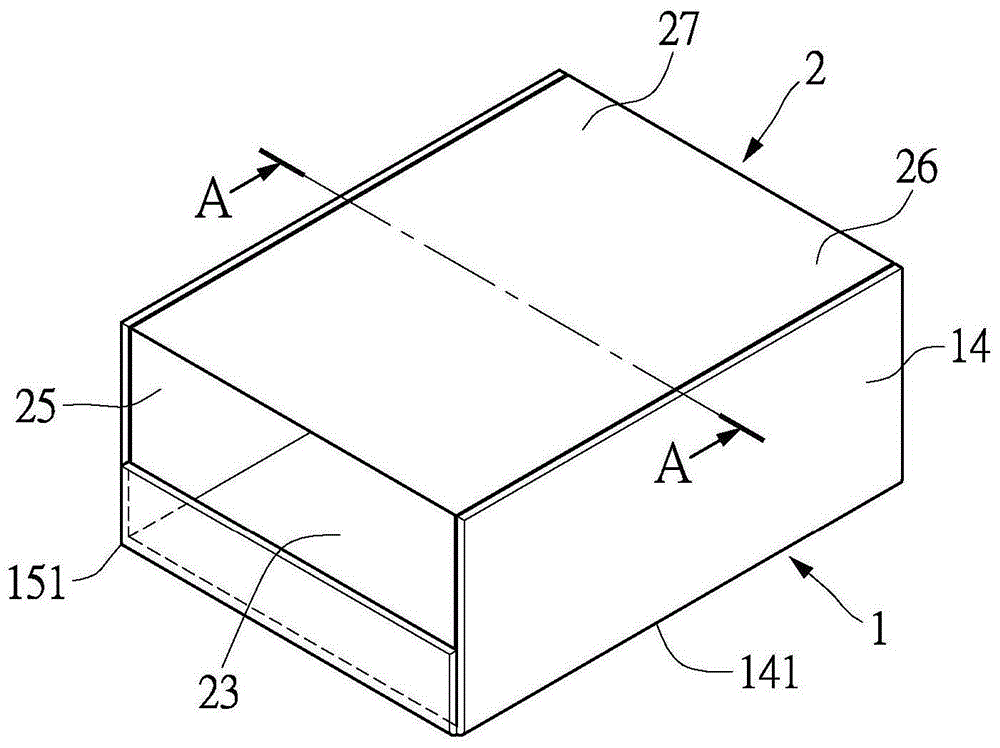
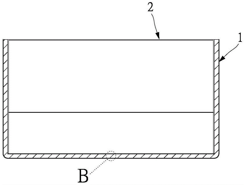
[0067] First, see Figure 1 to Figure 4 shown, where image 3 for figure 2 A cross-sectional schematic diagram of the A-A section, Figure 4 for image 3 Schematic enlarged detail of part B. The first embodiment of the present invention provides a composite heat dissipation structure H, which includes a carrier plate 1 and a heat sink 2 . The heat sink 2 can be disposed on the carrier plate 1 , and the composite heat dissipation structure H can be disposed on the object to be dissipated (not shown) to dissipate the heat of the object to be dissipated.
[0068] Then, as figure 1 , figure 2 and Figure 4As shown, specifically, the carrier board 1 has an aluminum substrate 11 and a first thermal diffusion radiation layer 12, and the aluminum substrate 11 has a first surface 111 and a second surface 112 opposite to the first surface 111, for example That is, the first surface 111 and the second surface 112 may be an upper surface and a lower surface, respectively. The f...
no. 2 example
[0077] First, see Figure 7 to Figure 9 As shown, the second embodiment of the present invention provides a composite heat dissipation structure H', which includes a carrier plate 1 and a heat sink 2 . Depend on Figure 7 and figure 1 It can be seen from the comparison of the second embodiment that the difference between the second embodiment and the first embodiment is that the composite heat dissipation structure H' provided by the second embodiment can additionally form a gas micro-channel S2.
[0078] Subject to the above, see Figure 4 As shown, the carrier board 1 has an aluminum substrate 11 and a first thermal diffusion radiation layer 12, the aluminum substrate 11 has a first surface 111 and a second surface 112 opposite to the first surface 111, wherein the first thermal diffusion radiation The layer 12 is disposed on the first surface 111 or the second surface 112 of the aluminum substrate 11 . The heat sink 2 is disposed on the carrier board 1 . The heat sink 2...
no. 3 example
[0083] First, see Figure 10 and Figure 11 As shown, the third embodiment of the present invention provides a composite heat dissipation structure H", which includes a carrier plate 1 and a heat sink 2. By Figure 10 and figure 1 By comparison, the difference between the third embodiment and the first embodiment is that the composite heat dissipation structure H" provided by the third embodiment, the carrier plate 1 of which can be formed by the first aluminum substrate 113 and the second aluminum substrate 114 respectively. In addition, the first aluminum substrate 113 and the second aluminum substrate 114 having the main body portion 13, the first side end portion 14 and the second side end portion 15, respectively, can be offset and overlapped with each other, so that the first aluminum substrate 113 and the second aluminum substrate 113 The first side end portion 14 and the second side end portion 15 on the aluminum substrate 114 surround the main body portion 13 .
[...
PUM
| Property | Measurement | Unit |
|---|---|---|
| thickness | aaaaa | aaaaa |
| thickness | aaaaa | aaaaa |
| thickness | aaaaa | aaaaa |
Abstract
Description
Claims
Application Information
 - R&D Engineer
- R&D Manager
- IP Professional
- Industry Leading Data Capabilities
- Powerful AI technology
- Patent DNA Extraction
Browse by: Latest US Patents, China's latest patents, Technical Efficacy Thesaurus, Application Domain, Technology Topic, Popular Technical Reports.
© 2024 PatSnap. All rights reserved.Legal|Privacy policy|Modern Slavery Act Transparency Statement|Sitemap|About US| Contact US: help@patsnap.com