


Quick Research
Generate reliable direction feasibility study reports for your R&D in just a few steps.

Technical Q&A
Discover and master advanced knowledge NOW. Basics, ideas, possibilities, all at once.

Find Solutions
As an expert in R&D theories, this can generate solutions to your technical problems instantly.

Evaluate Feasibility
Analyze your overall solution with one click, know your potential R&D risks in advance.

Monitor Landscape
Get weekly tech updates, stay abreast of the latest tech innovations and key insights.
Turbine generator with rotor arrangement capable of weakening polar frequency vibration winding
A turbogenerator and stator winding technology, applied to the shape/style/structure of winding conductors, electric components, magnetic circuit rotating parts, etc., can solve the problems of increasing the volume and weight of the motor, which is not a solution, and achieve motor The effect of compact structure, reduced reluctance, and reduced pole frequency and slot frequency radial electromagnetic excitation force
- Summary
- Abstract
- Description
- Claims
- Application Information
AI Technical Summary
Problems solved by technology
Method used
Image

Examples
Embodiment 1
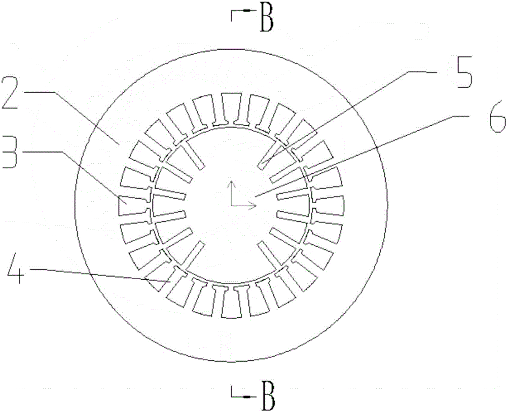
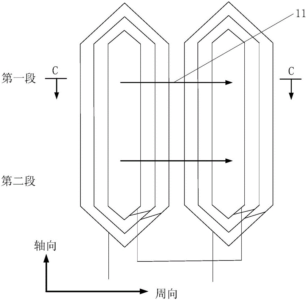
[0043] Such as Figure 7 Shown is the layout of the rotor damping winding 50 on the rotor iron core 60 of the turbogenerator of the present invention and the magnetic flux diagram of the magnetic field generated by it. In this embodiment, a 2-pole motor is taken as an example for illustration, and the stator has 24 slots. The first section 51 of the rotor damping winding is two coils A1 and A2, which are called group A coils, and the coils of group A are distributed in the circumferential direction. Here, the pitch of each coil is 1 / 3, spanning an electrical angle of 60 degrees, and can be set as required . The second segment 52 of the rotor damping winding is two coils B1 and B2, which are called group B coils. The coils of group B are distributed in the circumferential direction, and the span is the same as that of group A coils. The coils of group A and group B are arranged between the exciting windings 5, the coils of group A and group B with the same serial number are a...
Embodiment 2
[0053] Such as Figure 9 Shown is another form of the layout of the two-stage rotor vibration damping winding of the turbogenerator of the present invention and the magnetic field line diagram of the magnetic field generated by its electrification. Will Figure 7 The coils A1 and B1 are connected in reverse to form the coil A1, and the same axial magnetic field as the above-mentioned embodiment is generated after the current is passed through. At this time, the rotor core is still divided into two sections. The other coils are formed similarly and are arranged over the entire circumference of the motor.
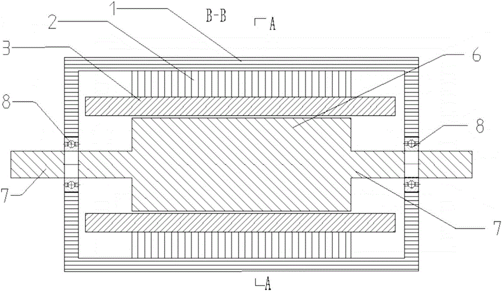
[0054] In the above-mentioned embodiments, for the convenience of description and understanding, the stator core and the stator winding are not divided into sections, but they can also be divided into two sections in fact.
PUM
 Abstract
Description
Claims
Application Information
 - R&D Engineer
- R&D Manager
- IP Professional
- Industry Leading Data Capabilities
- Powerful AI technology
- Patent DNA Extraction
Browse by: Latest US Patents, China's latest patents, Technical Efficacy Thesaurus, Application Domain, Technology Topic, Popular Technical Reports.
© 2024 PatSnap. All rights reserved.Legal|Privacy policy|Modern Slavery Act Transparency Statement|Sitemap|About US| Contact US: help@patsnap.com