
External current transformer assembly and gas insulated switchgear with same

A current transformer, external technology, applied in the direction of inductor, transformer/inductor coil/winding/connection, transformer/inductor shell, etc., can solve the problem of high cost, long shell and inner shield of current transformer, current Transformer size and other problems

Inactive Publication Date: 2017-01-11
SIEMENS AG
View PDF5 Cites 3 Cited by
  • Summary
  • Abstract
  • Description
  • Claims
  • Application Information

AI Technical Summary

Problems solved by technology

[0004] However, since the iron core and winding are arranged in the shell of the current transformer and are located in a high field intensity area, once the number of iron cores needs to be increased, the parameters need to be changed, or the larger TPY-level windings need to be used, the current transformer can only It is adjusted in its axial direction, so that the shell and inner shield of the entire current transformer become very long. Due to the large size of the current transformer, the operation of the entire gas insulated switchgear not only needs to meet the larger space requirements, but also lead to high cost

Method used


Image

  • External current transformer assembly and gas insulated switchgear with same
  • External current transformer assembly and gas insulated switchgear with same
  • External current transformer assembly and gas insulated switchgear with same

Examples


Embodiment Construction

[0040] In order to have a clearer understanding of the technical features, purposes and effects of the invention, the specific implementation manners of the present invention will now be described with reference to the accompanying drawings, in which the same reference numerals represent the same parts. In the drawings showing the respective embodiments, the same last two digits represent components with the same structure or similar structures but the same function.

[0041] In order to make the drawing concise, the parts related to the present invention are only schematically shown in each drawing, and they do not represent the actual structure of the product. In addition, to make the drawings concise and easy to understand, in some drawings, only one of the components having the same structure or function is schematically shown, or only one of them is marked.

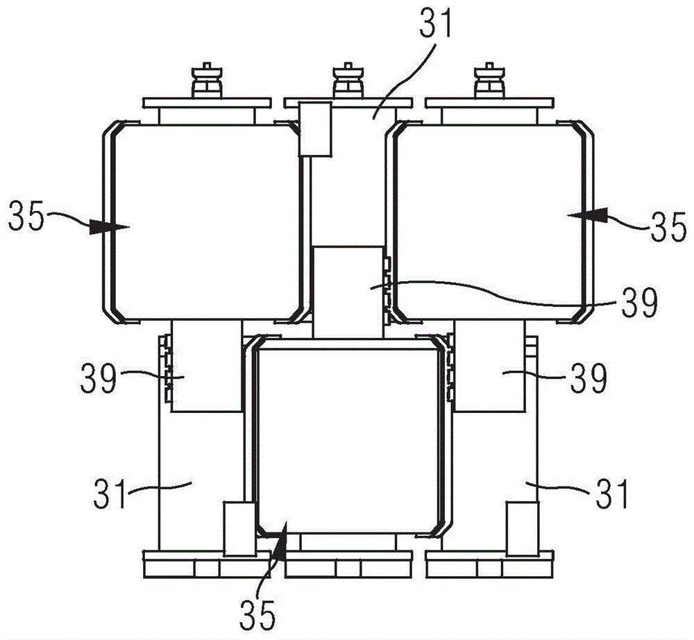
[0042] to combine Figure 3A and Figure 3B , which respectively show partial structural schematic diagrams of g...


PUM


Abstract

The invention provides an external current transformer assembly and a gas insulated switchgear with the same. The external current transformer assembly comprises a shell, a first flange, a second flange, a first partition plate, a second partition plate and at least one magnetic core and winding module, wherein the shell comprises a barrel; the first flange and the second flange are located at two ends of the barrel; the first partition plate is arranged outside the first flange; the second partition plate is located between the first partition plate and the second flange; the at least one magnetic core and winding module sleeves the barrel; the gas insulated switchgear comprises three phases; each phase is provided with a housing and comprises three external current transformer assemblies; and each external current transformer assembly is correspondingly arranged on one housing. According to the external current transformer assembly provided by the invention, the axial size of the shell can be effectively reduced; and the structure of the gas insulated switchgear is more compact through a special structure arrangement mode of three external current transformer assemblies, so that the occupied space of the gas insulated switchgear is effectively reduced.

Description

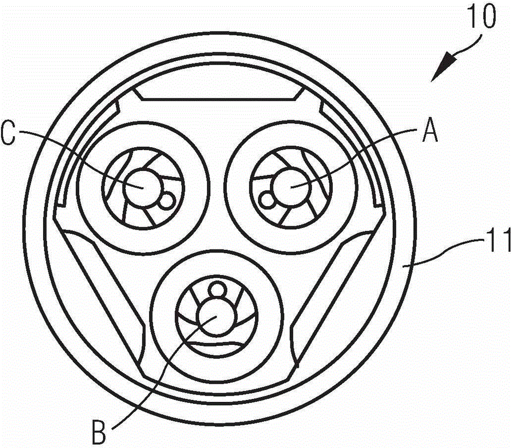
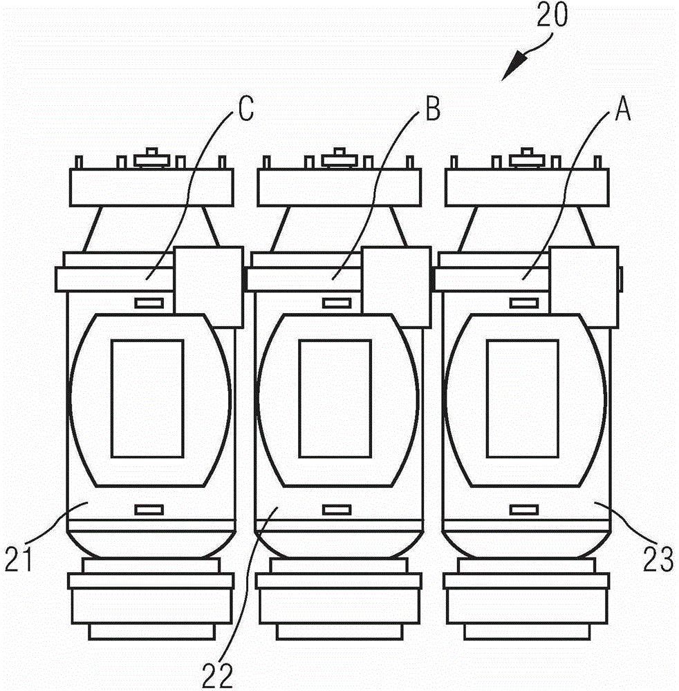
technical field [0001] The invention relates to the field of electrical equipment, in particular to an external current transformer assembly and a gas insulated switchgear with the same. Background technique [0002] It is known that the function of a current transformer is mainly to convert a large current into a standard small current in proportion to realize the standardization and miniaturization of measuring instruments, protection equipment and automatic control equipment. And the role of protection to ensure the safety of personal and equipment. [0003] Generally speaking, the current transformers used in gas insulated switchgear (GIS) in the prior art can be used to measure the magnitude of the current in the line, and they are mainly divided into the following two types. Such as figure 1 , which shows the first type of current transformer structure 10: three current transformers are installed axially parallel to each other inside the same housing 11, where the th...

Claims


Application Information

Patent Timeline
Patent Type & Authority Applications(China)
IPC IPC(8): H01F38/30H01F27/02H01F27/30H02B1/04
Inventor 农结神
Owner SIEMENS AG
Learn More