
A counterweight system for a magnetic levitation machining center

A machining center and magnetic levitation technology, which is applied in metal processing equipment, metal processing machinery parts, manufacturing tools, etc., can solve the problems of inability to meet the application needs of ultra-high precision, falling of the counterweight balance machine head, and short service life, etc. , to achieve the effect of simple structure, precise control and prolonging service life

Active Publication Date: 2017-12-29
福建省正丰数控科技有限公司
View PDF6 Cites 0 Cited by
  • Summary
  • Abstract
  • Description
  • Claims
  • Application Information

AI Technical Summary

Problems solved by technology

[0002] CNC machine tools in the machinery industry are driven axially by traditional screws. However, the screw structure will wear out during long-term use, resulting in poor axial precision and short service life.
In addition, the screw is a slender steel material, which reciprocates at a high speed for a long time. Affected by the environment and operating temperature, there is a physical phenomenon of thermal expansion and contraction, which cannot meet the needs of ultra-high-precision applications.
[0003] For this reason, the drive is gradually replaced by magnetic levitation (linear motor), but when the magnetic levitation (linear motor) machine tool moves up and down on the Z axis, there are problems of how to achieve counterweight balance and how to prevent the machine head from falling when the machine tool fails

Method used


Image

  • A counterweight system for a magnetic levitation machining center
  • A counterweight system for a magnetic levitation machining center
  • A counterweight system for a magnetic levitation machining center

Examples


Embodiment Construction

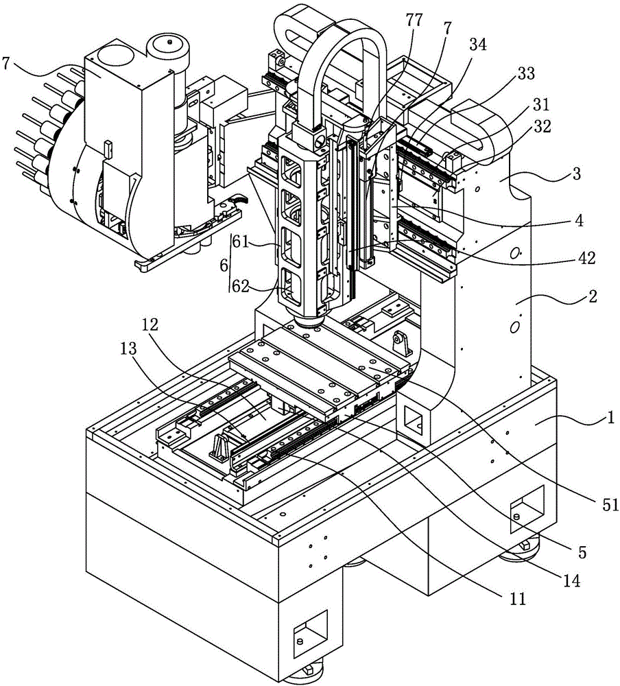
[0023] Such as Figure 1 to Figure 6 As shown, the maglev gantry machining center includes a base 1, two uprights 2 arranged at intervals on the base 1, a crossbeam 3 arranged between the two uprights 2, a tool magazine 7 arranged on one side of the crossbeam 3, and a ground movable horizontally and horizontally. The first sliding seat 4 arranged on the crossbeam 3, the second sliding seat 5 arranged on the base 1 that can move vertically and horizontally, the machine head mounting frame 63 that can be moved up and down on the first sliding seat 4, and installed on the The machine head 6 on the machine head mounting frame 63, the object stage 51 that is rotatably arranged on the second slide seat 5, is arranged between the second slide seat 5 and the object stage 51 for driving the object stage 51 to rotate The first DD motor, the X-axis moving mechanism arranged between the beam 3 and the first sliding seat 4, the Y-axis moving mechanism arranged between the base 1 and the se...


PUM


Abstract

The invention provides a magnetic suspension machining center counterweight system. The magnetic suspension machining center counterweight system comprises a counterweight cylinder which is arranged on a machine head mounting rack and connected with a machine head, a gas storage tank which is connected with the counterweight cylinder and filled with compressed gas, normally closed type pneumatic brakes which are arranged in the counterweight cylinder, a compressed air source which is connected with the pneumatic brakes through pipelines, and an electromagnetic valve which is arranged on the pipeline, connected with a control device and used for controlling the pipeline to be on and off. According to the magnetic suspension machining center counterweight system, the gas storage tank can supply compressed gas or oil to the counterweight cylinder during up-down movement of the machine head, so that the counterweight cylinder supports the machine head to offset the weight of the machine head, and therefore the machine head can move more stably, machining precision is improved, the output power requirement of a motor is reduced, the selection range of the motor is widened, and the service life of the motor is prolonged. When the machining center is powered off or pressure of the compressed gas is insufficient, the electromagnetic valve closes the corresponding pipeline and exhausts compressed air so that the pneumatic brakes can be closed to hold a piston rod tightly, and hence the machine head can stop moving, damage to the machine head is prevented, the structure is simple and control is accurate.

Description

technical field [0001] The invention relates to a counterweight system of a magnetic levitation machining center. Background technique [0002] CNC machine tools in the machinery industry are driven axially by traditional screw rods. However, the screw rod structure will wear out during long-term use, resulting in poor axial precision and short service life. In addition, the screw is a slender steel material, which reciprocates at high speed for a long time. Due to the influence of the environment and operating temperature, there is a physical phenomenon of thermal expansion and contraction, which cannot meet the needs of ultra-high-precision applications. [0003] For this reason, the drive is gradually replaced by magnetic levitation (linear motor), but when the magnetic levitation (linear motor) machine tool moves up and down on the Z axis, there are problems of how to achieve counterweight balance and how to prevent the machine head from falling when the machine tool fai...

Claims


Application Information

Patent Timeline
Patent Type & Authority Patents(China)
IPC IPC(8): B23Q11/00
CPCB23Q11/0017
Inventor 陈志明何轸炎谢进义王琦
Owner 福建省正丰数控科技有限公司
Learn More