
Filter technique based numerical control system acceleration and deceleration control method

A technology of acceleration and deceleration control and filtering technology, which is applied in the direction of digital control, digital technology network, electrical program control, etc., and can solve problems such as poor compatibility and complex implementation of S-shaped curve acceleration and deceleration planning software.

Active Publication Date: 2008-07-02
SHENYANG GOLDING NC & INTELLIGENCE TECH CO LTD
View PDF0 Cites 41 Cited by
  • Summary
  • Abstract
  • Description
  • Claims
  • Application Information

AI Technical Summary

Problems solved by technology

[0004] Aiming at the problem that the linear acceleration and deceleration planning of the numerical control system in the prior art has a sudden change in acceleration during the acceleration and deceleration phase, which causes severe mechanical vibration when the numerical control machine tool is moving, and the S-curve acceleration and deceleration planning software is complicated to implement and has poor compatibility. The purpose of the present invention is to provide a A method of acceleration and deceleration control of the CNC system based on filtering technology that not only effectively reduces the vibration of the machine tool, but also ensures that the processing shape and position will not be changed

Method used


Image

  • Filter technique based numerical control system acceleration and deceleration control method
  • Filter technique based numerical control system acceleration and deceleration control method
  • Filter technique based numerical control system acceleration and deceleration control method

Examples


Embodiment Construction

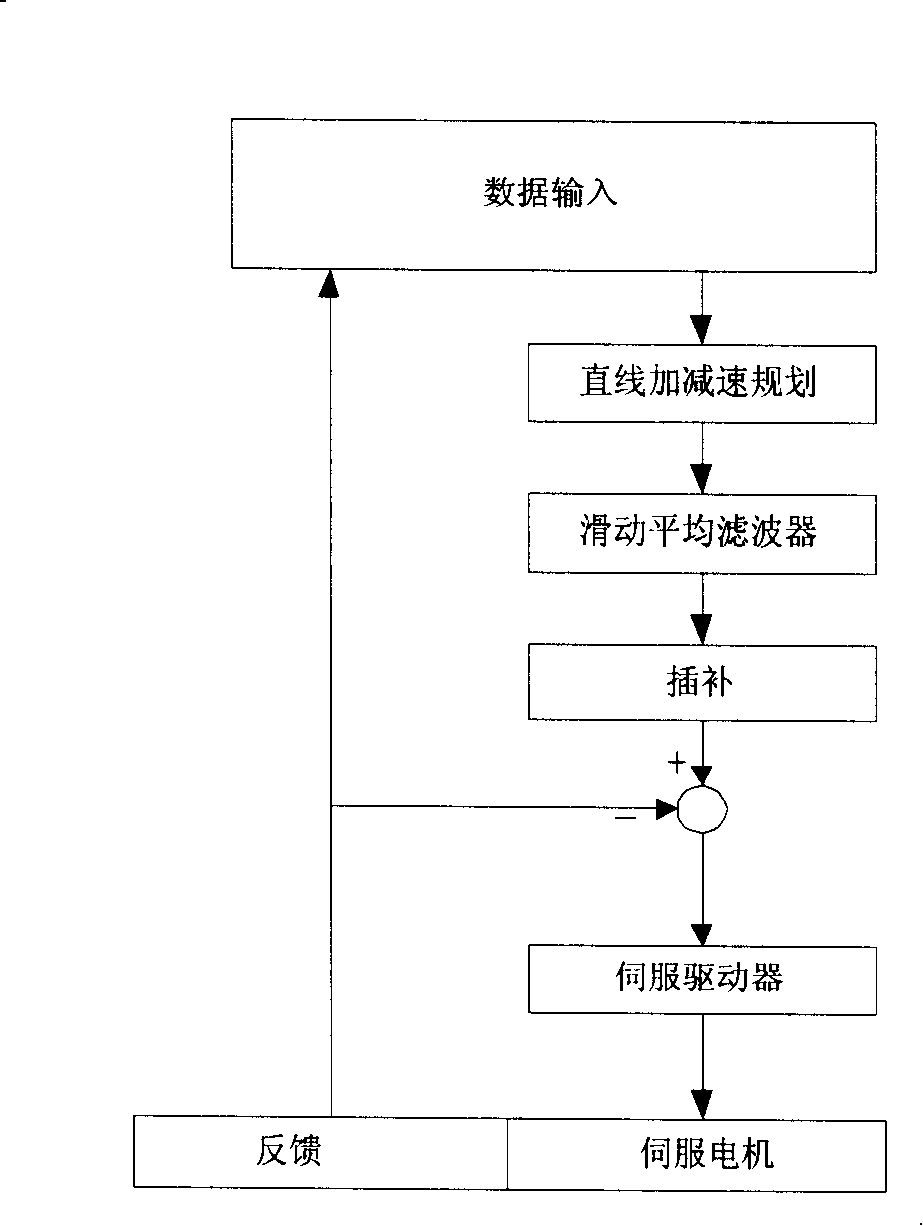
[0036] Such as figure 1 Shown, the inventive method comprises the following steps:

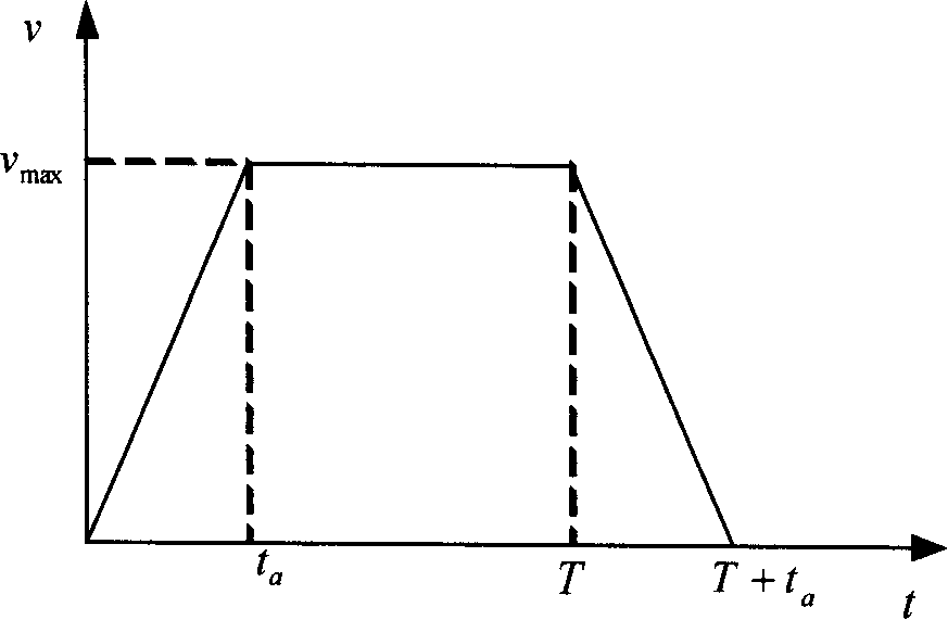
[0037] Use the input workpiece program data to plan linear acceleration and deceleration;

[0038] Perform sliding average filtering and filter compensation on the speed planned for linear acceleration and deceleration to obtain a new planned speed value and position value; interpolate the position value; control the servo motor through the position value obtained by the interpolation through the servo drive.

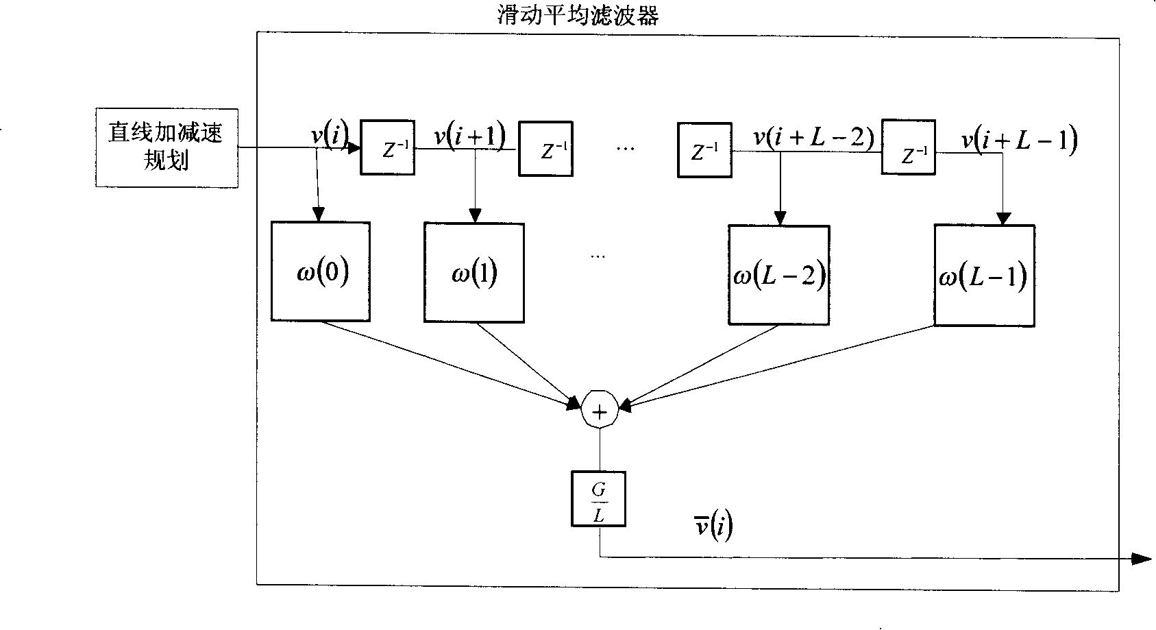
[0039] The speed of the straight-line acceleration and deceleration planning is done with a sliding average filtering process by adding a sliding average filter after the straight-line acceleration and deceleration planning to control the sudden change of the acceleration, specifically comprising the following steps: calculating the speed with the sliding average filtering speed planning method ;Select the filter length to change the smoothness of linear acceleration and deceleration, ...


PUM


Abstract

The invention relates to an acceleration or deceleration control method of numerical control system based on filter technique, which comprises the following steps: planning straight acceleration or deceleration by using the inputted workpiece program data; performing moving average filtering and filter compensation on the planned speed of the straight acceleration or deceleration to obtain a new planned speed value and a position value; performing interpolation on the position value; transmitting the interpolated position value to a servo driver in order to control a servomotor; wherein the moving average filtering of the planned speed of the straight acceleration or deceleration is implemented by adding a moving average filter after planning the straight acceleration or deceleration to control sudden changes of an accelerated speed, particularly comprising the following steps: calculating the speed with a method of planning the moving average filtering speed; changing the smooth degree of the straight acceleration or deceleration by selecting filter length (i.e. controlling the magnitude and the shape of the accelerated speed); and calculating a planned position according to the speed after filtering. The invention solves the vibration problem of a numerically-controlled machine tool during movement, and has the advantages of easy implementation, good compatibility and good flexibility.

Description

technical field [0001] The invention relates to a motion control method of a numerical control system, in particular to an acceleration and deceleration control method of a numerical control system based on filter technology. Background technique [0002] Acceleration and deceleration control is the core technology of the numerical control system. Commonly used acceleration and deceleration control methods include linear acceleration and deceleration, S-shaped curve acceleration and deceleration, etc. Although the linear acceleration and deceleration control method has a small amount of calculation and simple programming, there is a phenomenon of sudden acceleration and deceleration during the acceleration and deceleration phase, resulting in severe vibration of the machine tool, which is not suitable for high-speed machining of CNC machine tools. S-curve acceleration and deceleration is commonly used to control the sudden change of acceleration by limiting the jerk (that i...

Claims


Application Information

Patent Timeline
IPC IPC(8): G05B19/416H03H17/02
Inventor 胡韶华于东张景欣盖荣丽
Owner SHENYANG GOLDING NC & INTELLIGENCE TECH CO LTD
Learn More