Light motion assisting device and control method thereof
A power-assisted device and sports technology, applied in sports accessories, passive exercise equipment, muscle training equipment, etc., can solve the problems of complex control, difficulty in achieving sports assistance, easy to cause false triggering, etc., and achieve the effect of simple system structure
- Summary
- Abstract
- Description
- Claims
- Application Information
AI Technical Summary
Problems solved by technology
Method used
Image
Examples
Embodiment 1
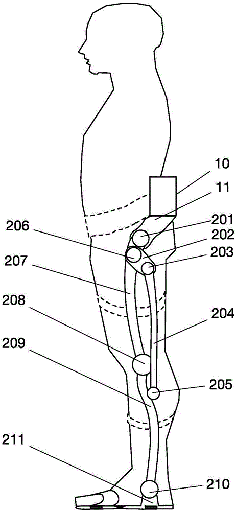
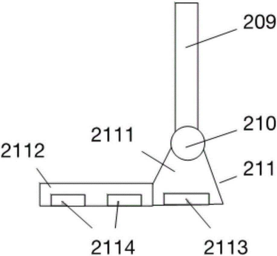
[0067] Such as figure 1 , figure 2 , Figure 9 with Figure 10 As shown, a portable sports assisting device includes a power system, a control system and an actuator. The power system includes a motor, a reducer, a clutch, a transmission shaft, a transmission sprocket, a transmission chain, a motor drive circuit and a power supply. The control system It includes a processor, a memory and a signal receiving circuit. The actuator includes a connecting rod structure that cooperates with the lower limbs of the human body to bear weight, and a sensor group. The sensor group includes a human body pressure monitoring system 291 for monitoring the pressure on the human foot, and a monitoring connection The mechanical pressure monitoring system 292 of the pressure on the rod structure, the human body pressure monitoring system 291 and the mechanical pressure monitoring system 292 respectively output signals to the control system, and the control system outputs control signals to the...
Embodiment 2
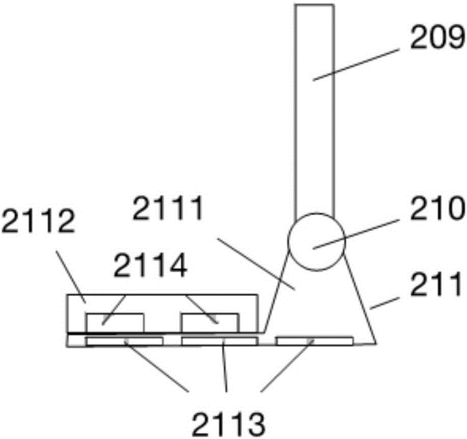
[0089] The control principle of this embodiment 2 and the structure of the motion assisting device are similar to those of embodiment 1, the difference is that the foot structure 211 adopts such as image 3 As shown in the structure, the foot structure 211 of this embodiment 2 includes a mechanical base 2111 and a human foot pad 2112, the lower part of the mechanical base 2111 extends forward and sideways, and a human foot pad is installed on the upper surface of the extension of the mechanical base 2111 2112, the lower part of the mechanical base 2111 is installed with a mechanical pressure sensor 2113 for monitoring the pressure of the connecting rod structure, and the mechanical pressure sensor 2113 covers the lower surface of the mechanical base 2111. The upper part of the mechanical base 2111 and the lower part of the human foot pad 2112 are installed with a human body plantar pressure sensor 2114 for monitoring the pressure on the human body foot. The human body plantar p...
Embodiment 3
[0091] The control principle of this embodiment 3 and the structure of the motion assisting device are similar to that of embodiment 2, the difference is that the foot structure 211 adopts such as Image 6 , Figure 7 structure shown. The bottom layer of the foot structure 211 contains a hard elastic thin plate 2115, on which a mechanical pressure sensor 2113 is fixed, on which the mechanical base 2111 is fixed, and the mechanical base 2111 can bear the connecting rod structure The pressure of the human body plantar pressure sensor 2114 is fixed on the mechanical base 2111, with a human body foot pad 2112 thereon. Adding an elastic thin plate 2115 at the bottom of the foot mechanism can enable the foot structure 211 to accurately measure human foot pressure and mechanical pressure in more complex terrains; the elastic thin plate can be an elastic manganese steel sheet or an elastic fiber sheet.
PUM
 Abstract
Description
Claims
Application Information
 - Generate Ideas
- Intellectual Property
- Life Sciences
- Materials
- Tech Scout
- Unparalleled Data Quality
- Higher Quality Content
- 60% Fewer Hallucinations
Browse by: Latest US Patents, China's latest patents, Technical Efficacy Thesaurus, Application Domain, Technology Topic, Popular Technical Reports.
© 2025 PatSnap. All rights reserved.Legal|Privacy policy|Modern Slavery Act Transparency Statement|Sitemap|About US| Contact US: help@patsnap.com


