
Turbine

A turbine and casing technology, applied in the field of turbines, can solve the problems of failure to achieve complete sealing effect, the energy efficiency conversion rate needs to be improved, and the complex structure of the casing, so as to achieve good sealing, reduce the difficulty of production and processing, and simplify the structure.

Active Publication Date: 2017-01-04
邓小波
View PDF9 Cites 5 Cited by
  • Summary
  • Abstract
  • Description
  • Claims
  • Application Information

AI Technical Summary

Problems solved by technology

[0006] 1. Due to the structure of multiple convex lines on the inner wall of the casing, the structure of the casing is complicated and the processing is difficult
[0007] 2. The conversion rate of energy efficiency needs to be improved, and there is still room for improvement in recoil power
Because the recoil power required for the rotation of the wheel disc 5 of the above-mentioned "new turbine" is realized through the structure of the protrusion 42 and the gear tooth 51; Less recoil power

Method used


Image

  • Turbine
  • Turbine
  • Turbine

Examples


Embodiment Construction

[0052] The present invention will be further described in detail below in conjunction with the accompanying drawings. Wherein, the descriptive terms such as up, down, left, right, etc. are used for the description, with the purpose of helping readers to understand, but not intended to limit.

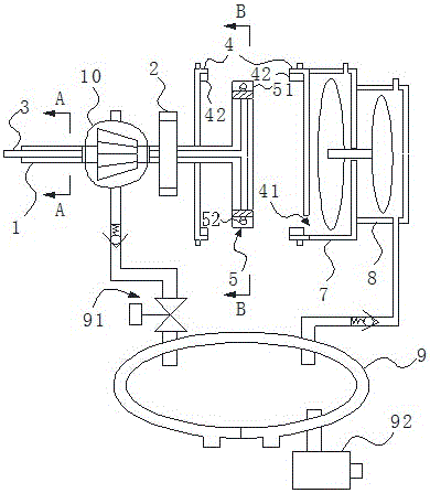
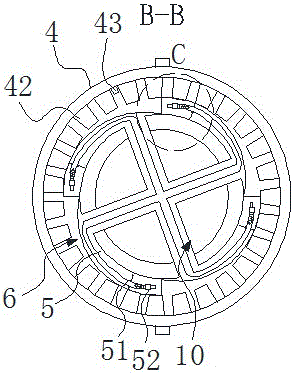
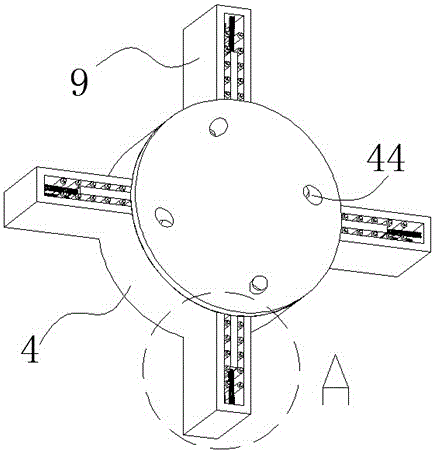
[0053] During specific implementation: if Figure 3 to Figure 10 As shown, the turbine includes a casing 4, a wheel disc 5, a wheel shaft 1 and a power take-off wheel; the casing 4 has a cylindrical inner cavity, and the outer surface of the casing 4 is provided with a row communicating with the inner cavity. Orifice 44;

[0054] The wheel 5 as a whole is coaxially and rotatably arranged in the inner cavity of the casing 4 and has a cylindrical structure with a cavity inside. Hollow gear teeth 51, each hollow gear tooth 51 is provided with a spray hole 53 on the side of each hollow gear tooth 51 (at a position away from the wheel disc 5), and the jet direction of the jet flow hole 53 i...


PUM


Abstract

The invention discloses a turbine. The turbine comprises a shell, a wheel disc, a wheel shaft and a power output wheel and is characterized by comprising rotary boosting structures, and each rotary boosting structure comprises a slider and an elastic reset part, wherein the slider is integrally in a strip plate structure, one end in the length direction of the slider slidably penetrates the shell along the radial direction of an inner cavity of the shell and is inserted into the inner cavity, the other end of the slider is positioned outside the inner cavity of the shell and abutted against the elastic reset part, the width direction of the slider is uniform with the axial direction of the inner cavity of the shell, and the width of the slider matches with the axial length of the inner cavity of the shell. The sliders are adjacent to drainage holes of the shell and positioned behind adjacent drainage holes correspondingly in the rotation direction of the wheel disc. The turbine is structurally simplified, and power output can be realized even the wheel disc is in low-speed rotation. By boosting chambers formed in the turbine, high airtightness is achieved, mechanical abrasion of components in the inner cavity of the shell of the turbine can be effective reduced, and accordingly reliability in operation of the turbine is realized.

Description

technical field [0001] The present invention relates to a turbine suitable for water, steam or gas turbines. Background technique [0002] A turbine is a rotating power machine that converts the energy of a gas (gas or steam) or liquid into mechanical work. A turbomachine or a gas turbine is a type of turbine. [0003] On January 23, 2013, the applicant proposed a technical solution named "Gas Turbine" (the authorized announcement number is CN103089437B), which solved the problem that the existing turbine has a complicated structure and uses high-temperature gas as the power source. The sealing device requires a high technical problem. [0004] On June 1, 2015, the applicant proposed a technical solution named "A New Type of Turbine" (the authorized announcement number is CN104963774B) (see Figure 1-2 ), the new turbine includes a wheel shaft 1, a power output wheel 2, a casing 4 and a wheel 5, the wheel 5 is located inside the casing 4, the wheel shaft 1 rotatably runs t...

Claims


Application Information

Patent Timeline
Patent Type & Authority Applications(China)
IPC IPC(8): F02C3/00F01D1/32F03B1/00
CPCF01D1/32F02C3/00F03B1/00Y02E10/20
Inventor 邓小波
Owner 邓小波
Learn More