Multistage centrifugal pump delivery chamber

A technology of extrusion chamber and centrifugal pump, which is applied in the direction of pumps, pump components, non-variable pumps, etc., which can solve the problems of difficult casting production, unstable operation, long axial distance, etc., and reduce the difficulty of casting and production processing , Improve operational reliability, and reduce the number of runners

Active Publication Date: 2017-05-31
西安航天泵业有限公司
View PDF7 Cites 1 Cited by
  • Summary
  • Abstract
  • Description
  • Claims
  • Application Information

AI Technical Summary

Problems solved by technology

The final stage of the segmental multi-stage pump adopts an annular extrusion chamber, and its structure is symmetrical, which is convenient for arranging through bars. However, this structure has many sealing leakage points and poor maintenance performance.
The horizontal split multi-stage pump adopts the spiral extrusion chamber, the axial distance of this structure is relatively long, it is difficult to process, assemble and cast, it is easy to cause unstable operation, and even reduce the service life of the bearing and the unit
When the flow rate of the pump is small and the head is high, if the spiral extrusion chamber is used, the cross-sectional area of ​​the flow channel of the casing is too small, so that the flow channel is narrow and long, casting production is difficult, and the axial dimension is large

Method used


Image

  • Multistage centrifugal pump delivery chamber
  • Multistage centrifugal pump delivery chamber
  • Multistage centrifugal pump delivery chamber

Examples


Embodiment Construction

[0014] Below in conjunction with accompanying drawing and specific embodiment content of the present invention is described in further detail:

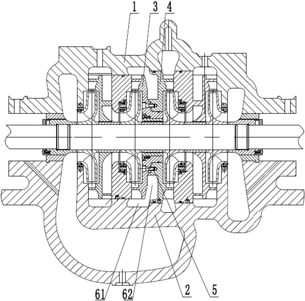
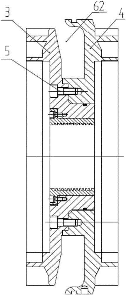
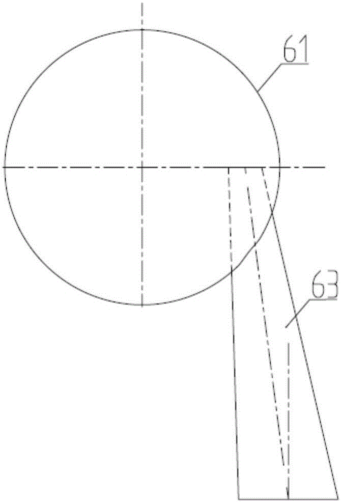
[0015] Such as figure 1 , figure 2 , image 3 The shown multi-stage centrifugal pump pressure chamber includes a first annular flow channel 62, a diffuser section 63 and a second annular flow channel 61 located outside the first annular flow channel 62, and the second annular flow channel 61 is arranged in the shell Inside the body, and located at the outlet of the first final guide vane 3, the first annular flow channel 62 is formed by the rear cover of the first final guide vane 3 and the rear cover of the second final guide vane 4 through joint fitting , the rear cover plate of the first final guide vane 3 and the rear cover plate of the second final guide vane 4 are fixedly connected by screws 5, the cross-sectional shape of the second annular flow channel 61 is rectangular; the diffuser section 63 is trumpet-shaped , located ...


PUM


Abstract

The invention relates to the field of fluid machines, and provides a multistage centrifugal pump delivery chamber which is small in axial size and easy to cast and assemble. The multistage centrifugal pump delivery chamber comprises a first annular runner, a diffusing section and a second annular runner located on the outer side of the first annular runner. The second annular runner is formed in the inner side of a shell and located at an outlet of a first final-stage guide vane. The areas of all sections of the second annular runner are equal. The first annular runner is formed by matching a rear cover plate of the first final-stage guide vane and a rear cover plate of a second final-stage guide vane. The diffusing section is in a horn shape, is located on one side of the second annular runner, and communicates with the second annular runner.

Description

technical field [0001] The invention relates to the field of fluid machinery, in particular to a pressure-out chamber of a multistage centrifugal pump. Background technique [0002] At present, the known extrusion chambers of multistage centrifugal pumps are spiral type extrusion chambers (volute type for short) and annular extrusion chambers. The final stage of the segmental multi-stage pump adopts an annular extrusion chamber, which has a symmetrical structure and is convenient for arranging piercing bars. However, this structure has many sealing leakage points and poor maintenance performance. The horizontal split multi-stage pump adopts a spiral extrusion chamber, which has a relatively long axial distance, making it difficult to process, assemble and cast, which will easily cause unstable operation and even reduce the service life of the bearing and the unit. When the flow rate of the pump is small and the head is high, if the spiral extrusion chamber is used, the cros...

Claims


Application Information

Patent Timeline
Patent Type & Authority Applications(China)
IPC IPC(8): F04D1/06F04D29/44F04D29/16
CPCF04D1/06F04D29/167F04D29/445
Inventor 宋怀德蒋婷李永乐赵寿堂张静张世存付岳峰习宁刚康渊博许文静张伟张鲁梁泽民
Owner 西安航天泵业有限公司
Why Eureka
Try Eureka