
High-strength composite board structure and mounting method thereof

A composite board, high-strength technology, applied in the direction of building structure, floor, covering/lining, etc., can solve the problems of harming human health, high water absorption rate of inorganic board, easy to burn, etc., to reduce residual deformation and residual stress, The effect of increasing the bearing area and increasing the foam density

Pending Publication Date: 2021-03-30
ZHEJIANG YASHA DECORATION
View PDF1 Cites 1 Cited by
  • Summary
  • Abstract
  • Description
  • Claims
  • Application Information

AI Technical Summary

Problems solved by technology

[0004] The above-mentioned patents have the following defects: 1. The structural strength is not enough. Due to the high water absorption rate of the inorganic board, the dimensional stability affected by humidity is poor. After compounding with polymer materials, the dimensional stability is affected by temperature due to the high linear expansion coefficient of the polymer material. Poor, when the surface flatness of the installation area is poor, the composite board is easily damaged; 2. It is easy to burn and is not suitable for areas with fire protection requirements; 3. It will release toxic gases and seriously pollute the natural environment such as the atmosphere. will harm human health

Method used


Image

  • High-strength composite board structure and mounting method thereof
  • High-strength composite board structure and mounting method thereof
  • High-strength composite board structure and mounting method thereof

Examples


Embodiment 1

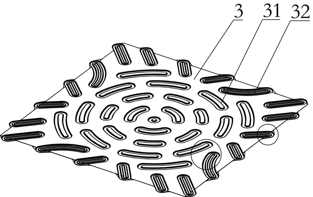
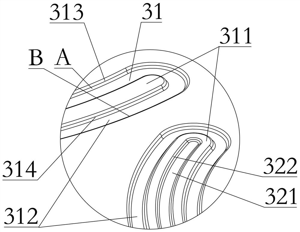
[0035] Embodiment one: if Figure 1-3 As shown, it is only one embodiment of the present invention, a high-strength composite panel structure, including a decorative panel part 1, a metal sheet part 3 located at the bottom of the decorative panel part 1, and used to connect the decorative panel part 1 and the adhesive layer 2 of the sheet metal part 3, the foam pad 4 at the bottom of the sheet metal part 3, and the sheet metal part 3 is provided with a first bearing part 31 located in the middle of the sheet metal part 3 , and the second load-bearing portion 32 located around the edge of the thin metal piece 3 , and the clamping portion 33 located around the thin metal piece 3 for connecting adjacent composite panels.

[0036] In the present invention, the sheet metal part 3 is formed by a stretching process, and the shape of the sheet metal part 3 is not limited to a rectangle, and may also be an equilateral triangle and a positive even-numbered polygon with sides not less th...

Embodiment 2

[0041] Embodiment two: if figure 2 and 4 As shown, it is only one of the embodiments of the present invention. On the basis of the first embodiment, the snap-in part 33 includes lap buckles located around the sheet metal part 3, and is connected with the edge of the sheet metal part 3 for lapping. Steps that connect to the buckle arc transition.

[0042] The first is the structure of the lap buckle. The lap buckle includes a second composite surface 331, a fourth annular section 333 for connecting the second composite surface 331 and the first supporting surface 312, and a fourth annular section 333 for connecting the second composite surface 331 and the first support surface 312. The fifth annular section 332 of the second support surface 321, the sixth annular section 334 for connecting the step and the first support surface 312, the height of the second composite surface 331 is lower than the height of the first composite surface 311, the second composite surface The hei...

Embodiment 3

[0045] Embodiment three: as figure 1 As shown, it is only one of the embodiments of the present invention. On the basis of Embodiment 1, a high-strength composite panel structure can be directly used for the kitchen and other areas with Class A fire protection requirements. The composite board formed by compounding with the decorative panel part 1 meets the Class A fire protection requirements; when used in areas without Class A fire protection requirements, the metal sheet part 3 with the foam pad 4 can be used.

[0046] It should be noted that the thin metal plate 3 and the foam pad 4 are integrally formed by molding and foaming. The specific process is that the metal plate is first stretched and formed, and then put into a molding and foaming mold, injected with foaming material, and passed through the molding mold. Foam molding. The sheet metal part 3 and the foam pad 4 adopt a molded integral molding process, which avoids the use of the adhesive layer 2 for secondary com...


PUM


Abstract

The invention provides a high-strength composite board structure and a mounting method thereof, and belongs to the technical field of assembly type decoration. The high-strength composite board structure comprises a decorative panel piece, a metal sheet piece, a bonding layer and a foaming pad, wherein a first bearing part, a second bearing part and a clamping part are arranged on the metal sheetpiece. The high-strength composite board structure is provided with the first bearing part and the second bearing part, the first bearing part is provided with a first annular section and a second annular section, the bearing area can be effectively increased, the bearing capacity of the composite board is improved, the first bearing part is annularly arranged, and the problem that a linear bearing weak area is formed on the composite board due to linear arrangement is solved; and the second bearing part is further provided with a third annular section, the bearing area can be further increased, the second bearing part is arranged in the diagonal direction, the rigidity of the vertex angle area of the composite board is further improved, and the problem that the composite board deforms dueto vertex angle stress concentration caused by uneven ground is solved.

Description

technical field [0001] The invention relates to the technical field of prefabricated decoration, in particular to a high-strength composite panel structure and an installation method thereof. Background technique [0002] Composite boards are boards composed of layers of different materials with different functions. They have the advantages of flat surface and high strength, so they are favored by the market. Therefore, composite boards are widely used in construction. However, since most of the core materials of the composite panels are composite panels made of plastic, gypsum and fibers, the composite panels have low strength. [0003] For example, the Chinese patent utility model patent CN207919965U discloses a floor substrate, including a substrate body, the substrate body is provided with grooves for placing heating pipelines, and the left and / or right sides of the substrate body are along its longitudinal direction. Buckles and / or slots are provided, and the buckles a...

Claims


Application Information

Patent Timeline
IPC IPC(8): E04F13/075E04F13/076E04F15/02E04F15/18E04F15/20
CPCE04F13/0866E04F15/02E04F15/02005E04F15/18E04F15/181E04F15/20E04F2201/01E04F2290/04E04F2290/043E04F2290/045
Inventor 丁欣欣丁泽成王文广周东珊余文钊武鹏
Owner ZHEJIANG YASHA DECORATION
Learn More