
Paint layer vibration polishing protection clamp for vane fan-shaped assemblies

A technology for protecting fixtures and sectors, which is applied in the direction of manufacturing tools, grinding workpiece holders, and surface polishing machine tools. It can solve problems such as delaying production cycles, peeling off the paint layer on the edge of the intake and exhaust, and increasing production costs. Accelerate the flow rate, The effect of enhancing the gloss decoration and preventing scratches and bumps

Active Publication Date: 2017-01-04
AECC AVIATION POWER CO LTD
View PDF7 Cites 4 Cited by
  • Summary
  • Abstract
  • Description
  • Claims
  • Application Information

AI Technical Summary

Problems solved by technology

[0005] In the process of processing, due to the large size and heavy weight of the fan-shaped components of the blade, during the three-dimensional spiral trajectory movement in the working chamber of the vibrating finishing machine, scratches and bumps inevitably occur between the components, resulting in the appearance of the surface paint layer. Chain-like friction marks or chain-like shallow damage, large-scale peeling off of the paint layer on the edge of the intake and exhaust, etc., resulting in complex rework of most parts, increasing production costs, and delaying the production cycle

Method used


Image

  • Paint layer vibration polishing protection clamp for vane fan-shaped assemblies
  • Paint layer vibration polishing protection clamp for vane fan-shaped assemblies

Examples


Embodiment Construction

[0022] Below in conjunction with accompanying drawing and specific embodiment the present invention is described in further detail:

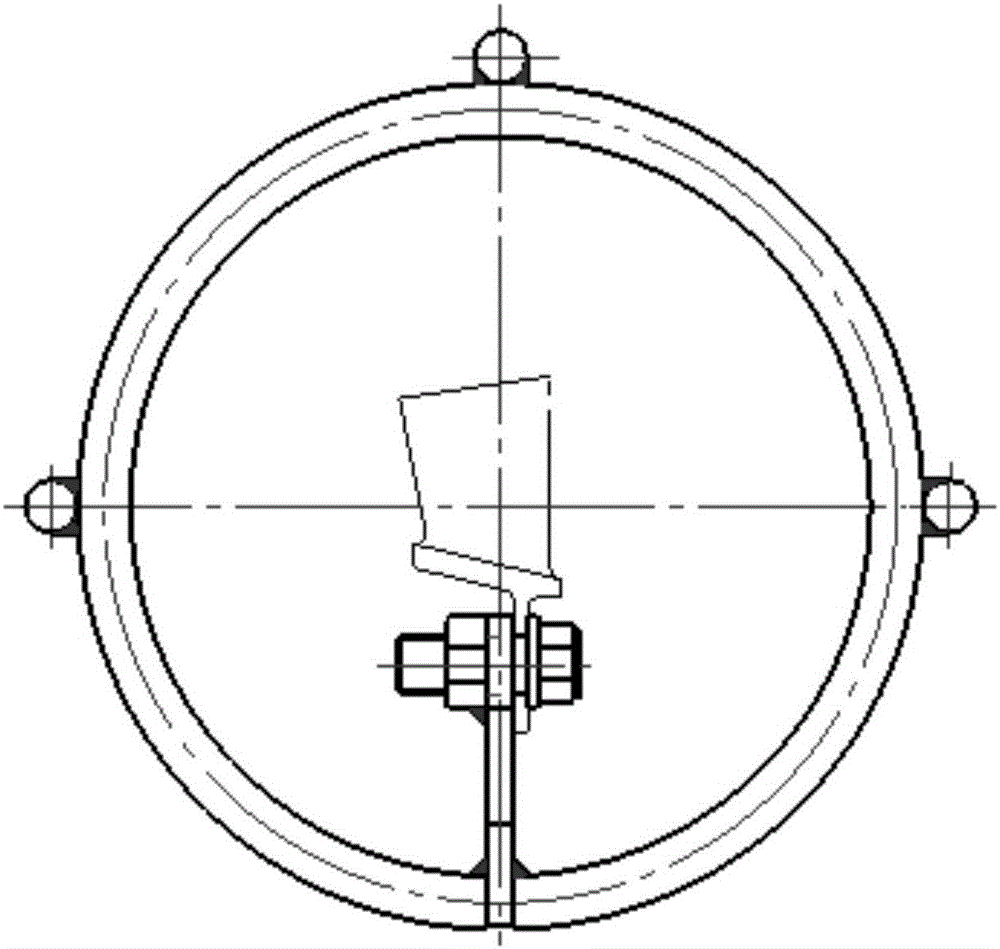
[0023] Such as figure 1 and figure 2 As shown, the blade fan-shaped assembly paint layer vibration light decoration protection fixture of the present invention includes a transverse installation rod 3, a plurality of transverse support rods 1 and a plurality of longitudinal rings 2; a plurality of longitudinal rings 2 are connected by a plurality of transverse support rods Together they form a cylindrical cage structure, and the transverse installation rods 3 used to fix the blade fan-shaped components are connected to a plurality of longitudinal rings 2, and the transverse installation rods 3 are located in the cage structure.

[0024] Further, it includes four longitudinal rings 2, three horizontal support rods 1 and one horizontal installation rod 3, and the three horizontal support rods 1 and one horizontal installation rod 3 are evenly ar...


PUM


Abstract

The invention discloses a paint layer vibration polishing protection clamp for vane fan-shaped assemblies. The paint layer vibration polishing protection clamp comprises a horizontal mounting rod, a plurality of horizontal supporting rods and a plurality of longitudinal circular rings. The longitudinal circular rings are connected through the horizontal supporting rods to form a cylindrical cage-type structure. The vane fan-shaped assemblies are fixed to the mounting rod in the cage-type structure and make spiral movement in the three-dimensional direction along with abrasives in a working cavity of a vibration polishing machine, and the cage-type structure effectively prevents the scratching and bumping between the vane fan-shaped assemblies. Meanwhile, the abrasives are machined through the gap between clamp structural members, and the free flowing of the fan-shaped assemblies is not affected.

Description

[0001] 【Technical field】 [0002] The invention belongs to the field of manufacturing blades of aero-engine compressors, and relates to a vibrating and light-decorating protective fixture for the paint layer of a fan-shaped component of a blade. [0003] 【Background technique】 [0004] At present, the high-voltage stator fan-shaped assembly, the blade material is martensitic stainless steel, and the surface of the blade body is coated with a layer of high-temperature resistant enamel MSRR9140 (Sermetel'W'-A). The blade assembly needs to be vibrated and polished to improve the paint layer of the blade body. The surface roughness is within 40μin. [0005] In the process of processing, due to the large size and heavy weight of the fan-shaped components of the blade, during the three-dimensional spiral trajectory movement in the working chamber of the vibrating finishing machine, scratches and bumps inevitably occur between the components, resulting in the appearance of the surface...

Claims


Application Information

Patent Timeline
Patent Type & Authority Applications(China)
IPC IPC(8): B24B31/02B24B41/06
CPCB24B31/0224B24B41/06
Inventor 吴俊乐罗红铎雷海峰江波张中坚杨俊杨薇杜龙梅
Owner AECC AVIATION POWER CO LTD
Learn More