Bottle cap transporting system

A conveying system and bottle cap technology, which is applied in the field of bottle cap manufacturing equipment, bottle cap and material packaging machinery, can solve the problems of high cap output efficiency, inconvenient use of caps, complex structure, etc., and achieve the effect of simple structure

Pending Publication Date: 2018-10-26
王安江
View PDF6 Cites 0 Cited by
  • Summary
  • Abstract
  • Description
  • Claims
  • Application Information

AI Technical Summary

Problems solved by technology

[0002] On the beverage and alcohol automatic filling production line, it is necessary to use a conveying mechanism to sort the disorderly stacked bottle caps in the hopper into a flow of bottle caps with correct orientation, and transport them to the sealing machine or canning machine; in the prior art, such as the Chinese patent CN2015208836736 discloses a capping structure, including a capping tube with an internal channel, a middle plate is arranged in the middle of the capping tube, and the middle plate divides the internal channel of the capping tube into capping channels for conveying bottle caps at the upper part And the air supply channel for supplying air to the cover conveying channel at the lower part, the head end of the air supply channel is connected to the air source, the middle plate is provided with multiple air out...

Method used


Image

  • Bottle cap transporting system
  • Bottle cap transporting system
  • Bottle cap transporting system

Examples


Embodiment 1

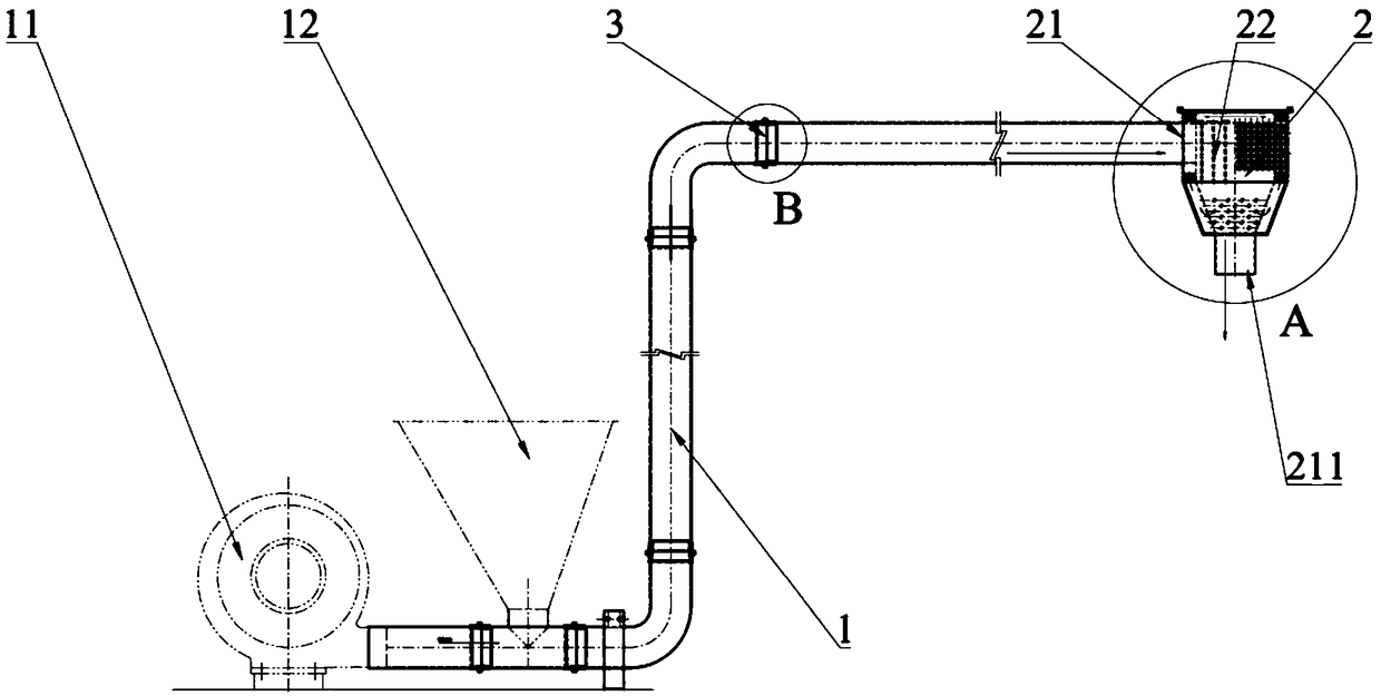
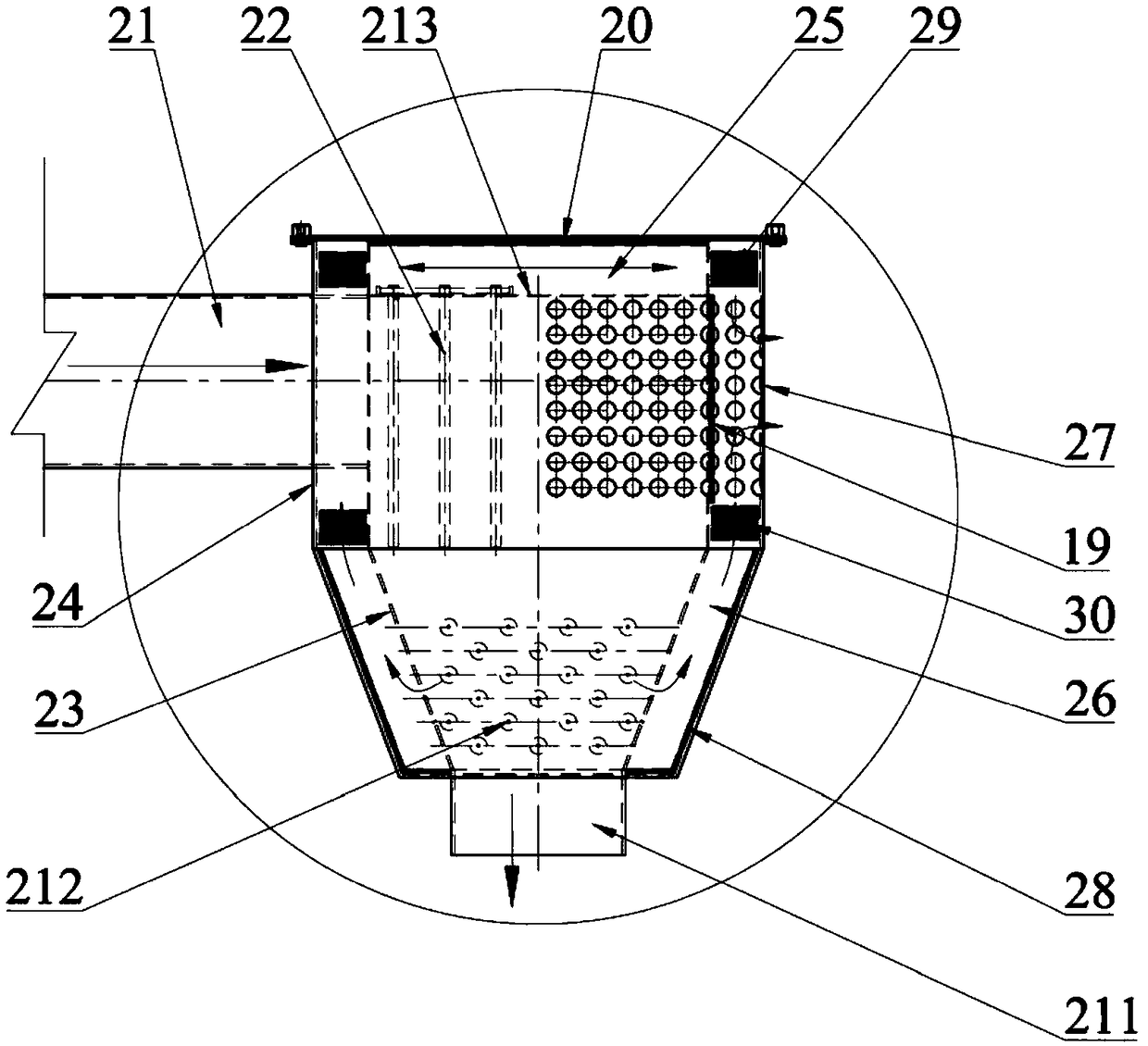
[0021] Such as figure 1 , 2 Embodiment 1 of the present invention shown is a bottle cap delivery system, comprising a delivery pipeline 1 and a pressure relief device 2; A bottle cap feeding port 12 is arranged on the top; the high-speed airflow and the bottle cap passing through the delivery pipeline 1 enter the interior of the pressure relief device 2 through the material inlet 21 on one side of the pressure relief device 2; enter the pressure relief device 2; The bottle cap of the device 2 rotates in a circular motion under the blowing of the high-speed airflow and hits the disturbing rod 22 inside the pressure relief device 2. The disturbing rod 22 swings with the air pressure to disturb the circular motion of the bottle cap. The bottle cap due to its own weight Free fall and discharge through material outlet 211.

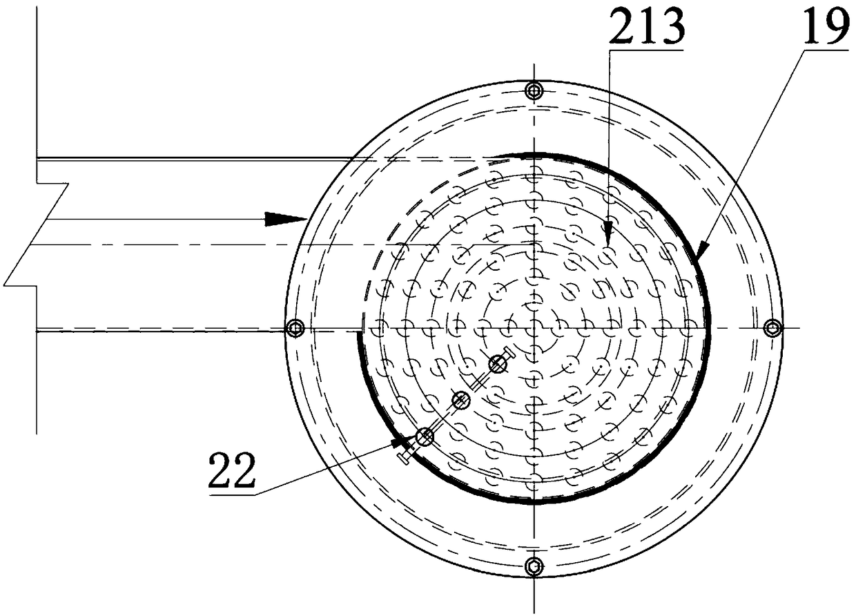
[0022] Such as figure 2 , 3 As shown, there are several disturbance rods 22, and the disturbance rods 22 are metal rods hanging inside the pressure relief...


PUM


Abstract

The invention discloses a bottle cap transporting system. The bottle cap transporting system comprises a transporting pipeline and a decompression device. The transporting pipeline is connected with adraught fan which is used for transporting high speed air flow; a bottle cap feed inlet is formed in the transporting pipeline. The high speed air flow and a bottle cap pass through the transportingpipeline and enter the decompression device through a material inlet on one side of the decompression device; and the bottle cap entering the decompression device rotates under blow of the high speedair flow in the circumferential direction and impacts a disturbing rod in the decompression device; the disturbing rod swings with air pressure to disturb circumferential movement of the bottle cap, and the bottle cap falls freely due to self-weight and is discharged through a material outlet. The bottle cap transporting system is simple in structure and convenient to use, and the condition that the bottle cap is bumped and scratched is prevented.

Description

technical field [0001] The invention relates to the technical field of bottle cap manufacturing device transportation, bottle cap and material packaging machinery, in particular to a bottle cap conveying system. Background technique [0002] On the beverage and alcohol automatic filling production line, it is necessary to use a conveying mechanism to sort the disorderly stacked bottle caps in the hopper into a flow of bottle caps with correct orientation, and transport them to the sealing machine or canning machine; in the prior art, such as the Chinese patent CN2015208836736 discloses a capping structure, including a capping tube with an internal channel, a middle plate is arranged in the middle of the capping tube, and the middle plate divides the internal channel of the capping tube into capping channels for conveying bottle caps at the upper part And the air supply channel for supplying air to the cover conveying channel at the lower part, the head end of the air supply ...

Claims


Application Information

Patent Timeline
IPC IPC(8): B65G53/60B65G53/40B67B3/06
CPCB65G53/40B65G53/60B67B3/06B65G2207/32
Inventor 王安江谭燕
Owner 王安江
Why Eureka
Try Eureka