Novel floating positioning horizontal broaching plate for broaching machine

A positioning horizontal and new type of technology, applied in broaching machines, broaching devices, metal processing equipment, etc., can solve problems such as misalignment of center lines, and achieve practical, high-efficiency, and high-quality results

Inactive Publication Date: 2017-01-04
洛阳华冠齿轮股份有限公司
View PDF4 Cites 0 Cited by
  • Summary
  • Abstract
  • Description
  • Claims
  • Application Information

AI Technical Summary

Problems solved by technology

[0002] As a mechanical processing industry, we often encounter some stepped disc parts. It is necessary to position and broach the inner spline based on the processed outer circle and end face. From the perspective of current technology and equipment, some high-end enterprises, the newly purchased broaching The internal spline equipment is a high-end vertical broaching machine, and the accuracy of the internal spline is relatively easy to guarantee; but for some traditional old enterprises or small-scale private enterprises, most of them still use traditional horizontal broaching machines
When broaching parts on a horizontal broaching machine, the broaching force of the broaching tool does not coincide with the center line of the positioning outer circle due to the combined gravity of the part being pulled and the weight of the broach, resulting in the final broached part , using its own internal spline as a benchmark to detect the end face and outer circle end runout and radial runout of the part, and there is an out-of-tolerance phenomenon; therefore, a floating positioning is developed to ensure that the broaching force of the broach is always perpendicular to the end face of the part during broaching. A new type of horizontal pulling plate that improves efficiency and precision is of great practical significance

Method used


Image

  • Novel floating positioning horizontal broaching plate for broaching machine
  • Novel floating positioning horizontal broaching plate for broaching machine

Examples


Embodiment Construction

[0016] The present invention will be further described below in conjunction with the accompanying drawings.

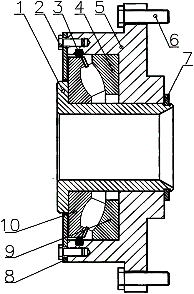
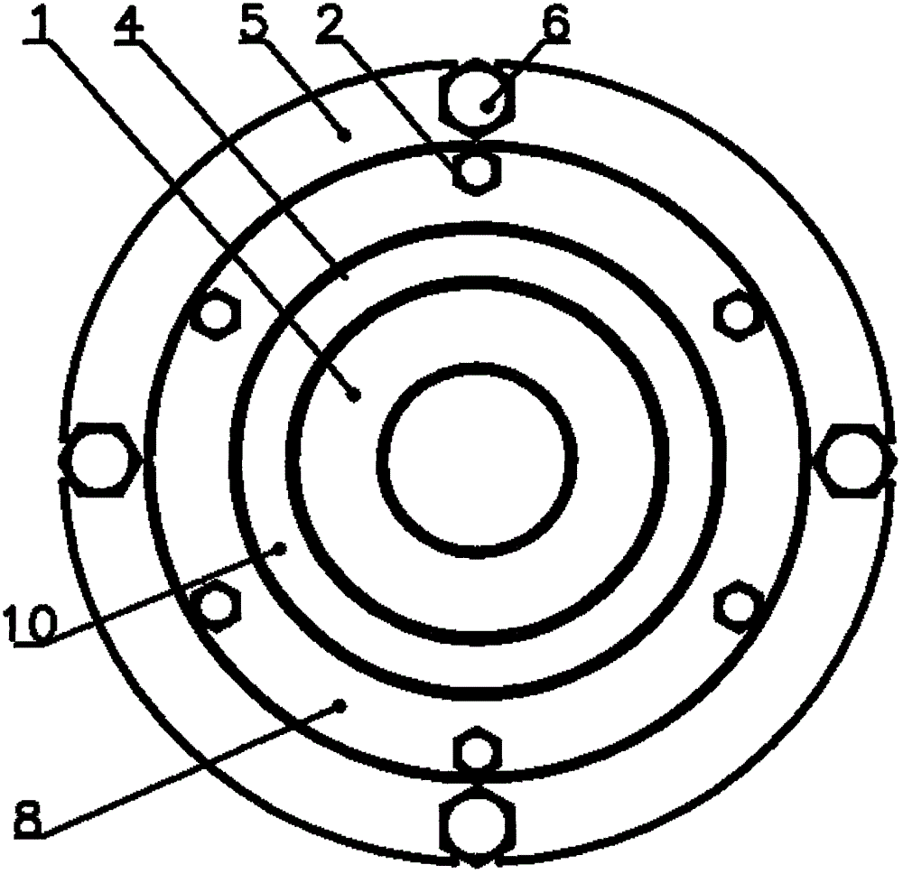
[0017] Such as figure 1 , figure 2 As shown, a new type of floating positioning horizontal broaching puller, when the present invention is assembled as a whole, firstly press the bearing seat ring 9 into the cavity of the bearing seat type puller 5 according to the small interference fit, so as to ensure The end surface of the bearing race 9 is firmly attached to the bottom surface of the cavity of the bearing seat puller 5, and then the journal of the quick-change bushing 1 is lightly pressed into the inner diameter of the bearing shaft ring 10 according to a small interference fit, so that the quick-change bushing The end face of the step of 1 is closely attached to the end face of the bearing shaft ring 10; install the O-shaped rubber ring 3 in the O-shaped sealing ring groove in the cavity of the bearing housing type pull plate 5, and install the bearing shaft ri...


PUM


Abstract

The invention relates to a novel floating positioning horizontal broaching plate for a broaching machine. The phenomenon of extremely poor end jump and radial jump of the end face and outer circle of a finally broached part which is detected by taking own internal spline as a reference usually due to the fact that the broaching force of a broaching tool is not overlapped with the center line of a positioning outer circle under the gravity coaction of the weight of the broached part and the weight of the broaching tool when the part is broached by a conventional horizontal broaching machine is eliminated, and a quick changing bushing matched with the size of the outer circle of the broached part is adopted for implementation. With adoption of such a structure, the joint influence of the self weight of the broached part and the weight of the broaching tool is eliminated, and when the specification of the part to be broached is replaced, only the quick changing bushing matched with the size of the outer circle of the part to be broached is required to be replaced. In addition, perpendicularity between the center line of a broached internal spline and the end face of a positioning reference can also be ensured, the accuracy requirement of the broached part is met, and practicability, high efficiency and stable quality are ensured.

Description

technical field [0001] The invention belongs to the field of mechanical manufacturing, and in particular relates to a novel puller of a floating positioning horizontal broaching machine. Background technique [0002] As a mechanical processing industry, we often encounter some stepped disc parts. It is necessary to position and broach the inner spline based on the processed outer circle and end face. From the perspective of current technology and equipment, some high-end enterprises, the newly purchased broaching The internal spline equipment is a high-end vertical broaching machine, and it is easier to guarantee the accuracy of the internal spline; however, for some traditional old enterprises or small-scale private enterprises, most of them still use traditional horizontal broaching machines. When broaching parts on a horizontal broaching machine, the broaching force of the broaching tool does not coincide with the center line of the positioning outer circle due to the com...

Claims


Application Information

Patent Timeline
IPC IPC(8): B23D41/06
CPCB23D41/06
Inventor 孟江涛刘泽虎梅利红
Owner 洛阳华冠齿轮股份有限公司
Why Eureka
Try Eureka