Machine tool control device and machine tool provided with the control device
一种控制装置、机床的技术,应用在机床领域,能够解决未考虑振动频率等问题
- Summary
- Abstract
- Description
- Claims
- Application Information
AI Technical Summary
Problems solved by technology
Method used
Image
Examples
Embodiment 1
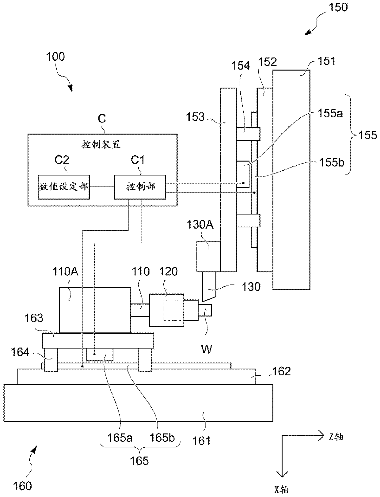
[0044] figure 1 It is a figure which shows the outline|summary of the machine tool 100 provided with the control apparatus C of 1st Example of this invention.
[0045] The machine tool 100 includes a spindle 110 and a cutting tool table 130A.
[0046] A chuck 120 is provided at the front end of the spindle 110 .
[0047] The workpiece W is held by the spindle 110 via the chuck 120 , and the spindle 110 constitutes a workpiece holding unit for holding the workpiece.
[0048] The spindle 110 is supported by the headstock 110A so as to be rotationally driven by the power of a spindle motor (not shown).
[0049] As the above-mentioned spindle motor, a conventionally known built-in motor or the like formed between the headstock 110A and the spindle 110 in the headstock 110A can be considered.
[0050] The headstock 110A is mounted on the bed side of the machine tool 100 so as to be movable in the Z-axis direction serving as the axial direction of the spindle 110 by the Z-axis di...
Embodiment 2
[0138] The second embodiment changes the parameters, conditions, etc. of the first embodiment. Most of the elements are common to the first embodiment. Therefore, the detailed description of the common items is omitted, and the differences are described below.
[0139] In the machine tool 100 of the second embodiment, the user sets the rotational speed S to the control unit C1 via the numerical value setting unit C2 and the like.
[0140] The setting of the rotation speed S to the control unit C1 can be performed by not only inputting the value of the rotation speed S into the control unit C1 as a parameter value, but also by writing the value of the rotation speed S in a machining program, for example.
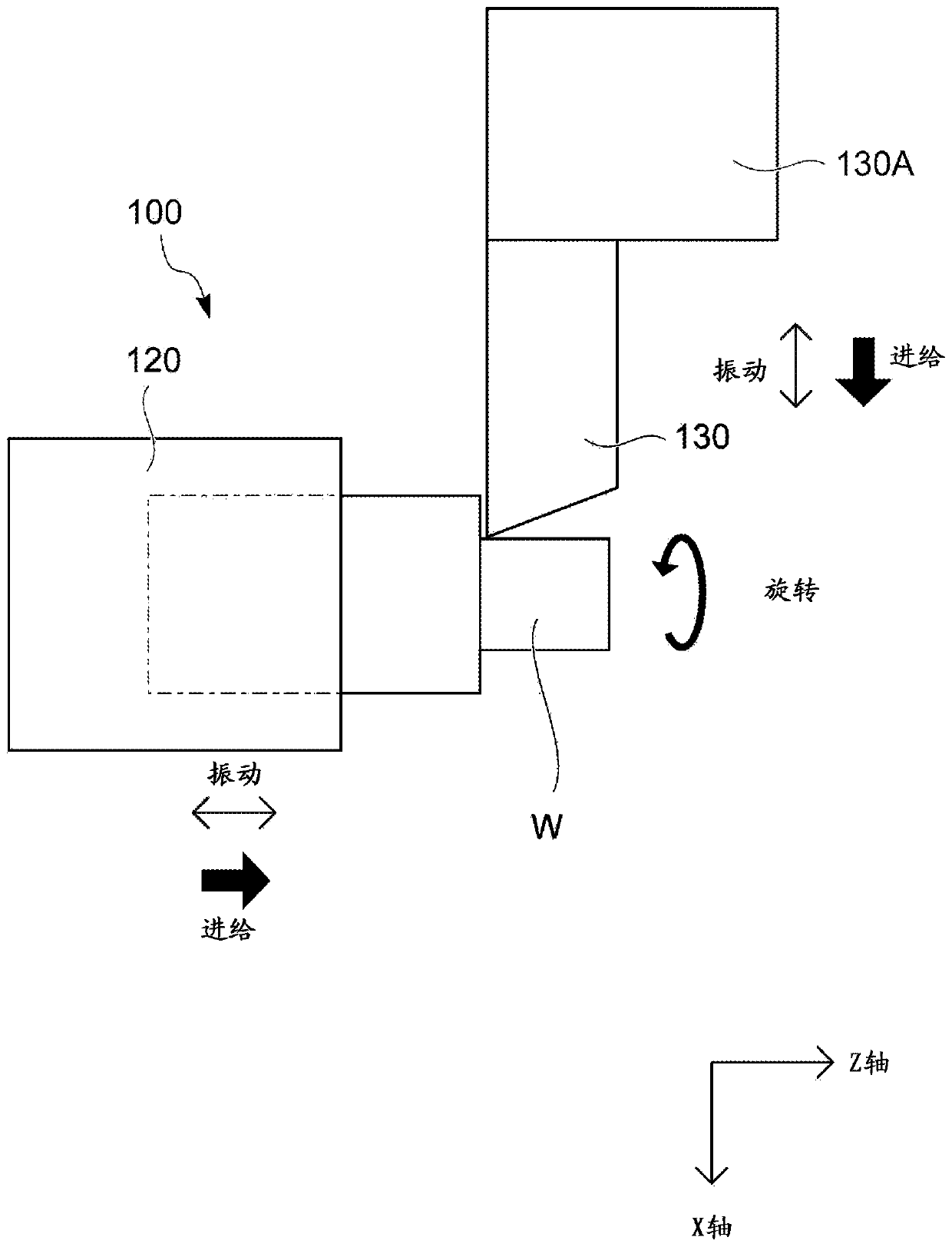
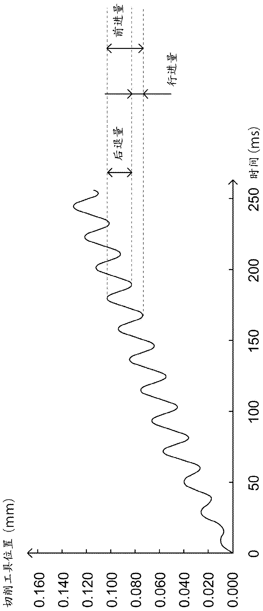
[0141] The control unit C1 controls to rotate the main shaft 110 based on the set rotation speed S, and to move the headstock 110A or the cutting tool table 130A while vibrating back and forth so that the cutting tool 130 moves in the machining feed direction while vibrating b...
Embodiment 3
[0160] For the third embodiment, most of the elements are common to the first embodiment and the second embodiment, so the detailed description of the common matters will be omitted, and the differences will be described below.
[0161] In the machine tool 100 of the third embodiment, similar to the first embodiment or the second embodiment, if the user sets two (rotational speed S and vibration number N) or one (rotational speed S) of the three parameters to If it is set to the control unit C1, it is possible to make the cutting tool 130 move along the above-mentioned machining feed direction under the condition that is relatively close to the rotation speed S and the vibration number N expected by the user or based on the preset rotation speed S. The reciprocating vibration of the workpiece W is smoothly cut while feeding in the machining feed direction to separate the chips.
[0162] Such as Figure 8A shown, with Figure 4 Similarly, the main shaft rotates once and the c...
PUM
 Abstract
Description
Claims
Application Information
 - R&D Engineer
- R&D Manager
- IP Professional
- Industry Leading Data Capabilities
- Powerful AI technology
- Patent DNA Extraction
Browse by: Latest US Patents, China's latest patents, Technical Efficacy Thesaurus, Application Domain, Technology Topic, Popular Technical Reports.
© 2024 PatSnap. All rights reserved.Legal|Privacy policy|Modern Slavery Act Transparency Statement|Sitemap|About US| Contact US: help@patsnap.com


