
Structure for measuring temperature and voltage inside FPGA in real time

A technology of internal temperature and real-time measurement, applied in the direction of measuring electricity, measuring electrical variables, measuring devices, etc., can solve the problems of wasting hardware resources, unable to monitor FPGA working temperature and working voltage in real time, and achieve the effect of prolonging the life of the chip

Inactive Publication Date: 2016-12-14
58TH RES INST OF CETC
View PDF5 Cites 4 Cited by
  • Summary
  • Abstract
  • Description
  • Claims
  • Application Information

AI Technical Summary

Problems solved by technology

[0003] In the prior art, during the general FPGA development process, internal voltages that need to be tested, such as power supply voltage, programmable memory unit power supply voltage SRAMVDD, and internal bandgap reference BANDGAP output, will be tested through a special NC PIN pin. After the chip test is completed It will no longer be used, which will waste part of the hardware resources. At the same time, in actual use, the user cannot monitor in real time whether the operating temperature and operating voltage of the FPGA are within a reasonable range.

Method used


Image

  • Structure for measuring temperature and voltage inside FPGA in real time
  • Structure for measuring temperature and voltage inside FPGA in real time
  • Structure for measuring temperature and voltage inside FPGA in real time

Examples


Embodiment Construction

[0018] Embodiments of the present invention will be described in detail below in conjunction with the accompanying drawings.

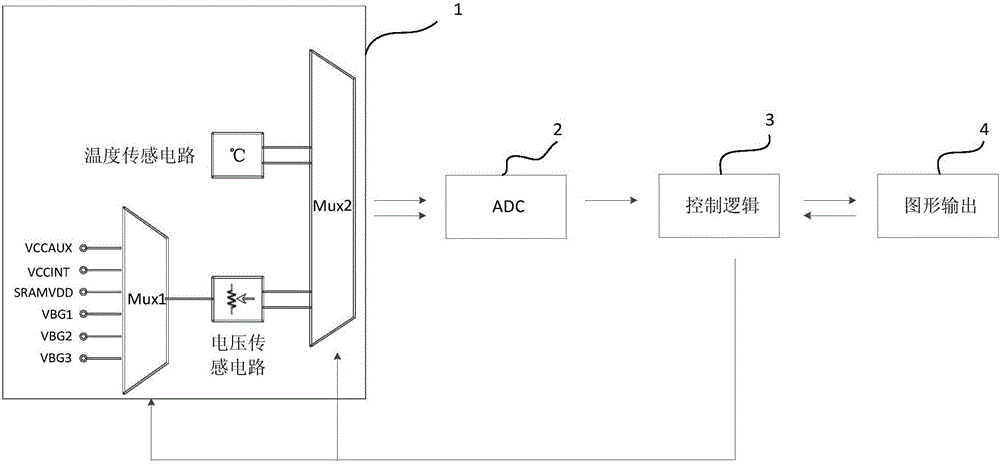
[0019] Such as figure 1 As shown, a structure capable of real-time measurement of the internal temperature and voltage of the FPGA includes a temperature and voltage input selection module 1 for selecting the temperature and voltage to be measured; an analog-to-digital conversion module ADC 2 for converting the measured analog signal It is a digital signal; the control logic module 3 is used to control the channel mode and process the digital measurement results; the graphic output module 4 is used to form a curve on the computer screen of the measured value on the chip.

[0020] Wherein, the temperature and voltage input selection module 1 includes two multiplexers MUX1 and MUX2, a voltage sensing circuit, and a temperature sensing circuit, and the selection control signals of the two multiplexers come from the control logic module. The input termin...


PUM


Abstract

The invention relates to a structure for measuring the temperature and voltage inside an FPGA in real time. The structure comprises a temperature and voltage input selection module used for selecting temperature and voltage needing to be measured, an analog-to-digital conversion (ADC) module used for converting measured analog quantity into digital quantity, a control logic module used for controlling the channel mode and processing the digital measurement result, and a graphic output module used for forming a curve on a computer screen with the measurement values on a chip. The structure has the advantages as follows: real-time measurement of the temperature and voltage inside an FPGA is realized, and measurement is convenient and visual; the number of modules and pins specially used for voltage test in an FPGA is reduced; and when the temperature and voltage inside an FPGA are not within a set reasonable range, the alarm output signal is effective, the alarm is raised, and the FPGA chip is protected effectively.

Description

technical field [0001] The invention relates to a structure capable of measuring internal temperature and voltage of FPGA in real time, and belongs to the technical field of programmable logic devices. Background technique [0002] Programmable logic device (FPGA), based on repeated configuration storage technology, completes circuit modification by re-downloading programming, has the advantages of short development cycle, low cost, low risk, and easy maintenance and upgrade of electronic systems, so it has become an integrated circuit Chip mainstream. Programmable logic devices mainly include control system, programmable logic unit, digital signal processing DSP, storage unit BRAM and some high-speed interfaces, clock modules and IP cores. [0003] In the prior art, during the general FPGA development process, internal voltages that need to be tested, such as power supply voltage, programmable memory unit power supply voltage SRAMVDD, and internal bandgap reference BANDGAP...

Claims


Application Information

Patent Timeline
Patent Type & Authority Applications(China)
IPC IPC(8): G01R31/3185
CPCG01R31/318519
Inventor 黄栋徐玉婷张胜广耿扬
Owner 58TH RES INST OF CETC
Learn More