
Swelling pressure composite forming method for large-section-difference special-shaped section pipe fitting

A compound forming and large cross-section technology, which is applied in the field of expansion-compression compound forming, can solve the problem that the pipe fittings with complex cross-section shapes and special-shaped cross-sections cannot be obtained, and achieve the effect of uniform distribution of circumferential wall thickness and low requirements

Active Publication Date: 2016-12-14
HARBIN INST OF TECH
View PDF5 Cites 32 Cited by
  • Summary
  • Abstract
  • Description
  • Claims
  • Application Information

AI Technical Summary

Problems solved by technology

[0006] In order to solve the problem that the existing forming method cannot obtain the pipe fittings with large cross-section difference and complex special-shaped cross-section that meet the requirements of cross-sectional shape, size and wall thickness distribution, the present invention proposes a method for expanding and compressing composite forming of pipe fittings with large cross-section and different cross-section

Method used


Image

  • Swelling pressure composite forming method for large-section-difference special-shaped section pipe fitting
  • Swelling pressure composite forming method for large-section-difference special-shaped section pipe fitting
  • Swelling pressure composite forming method for large-section-difference special-shaped section pipe fitting

Examples


specific Embodiment approach 1

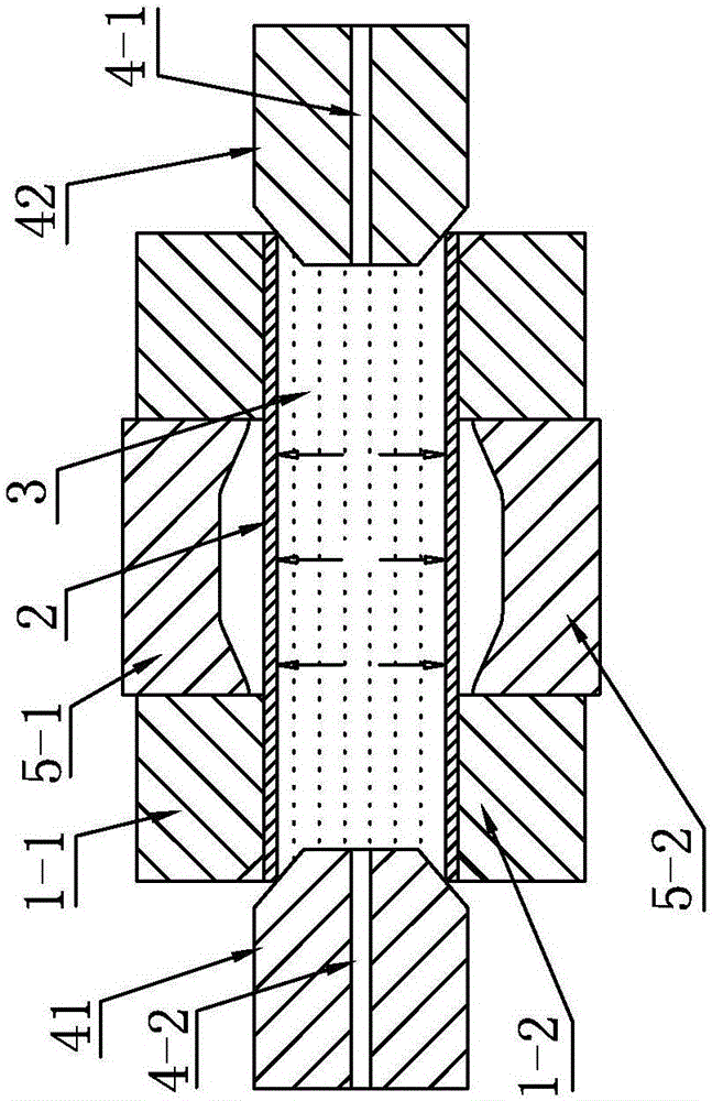
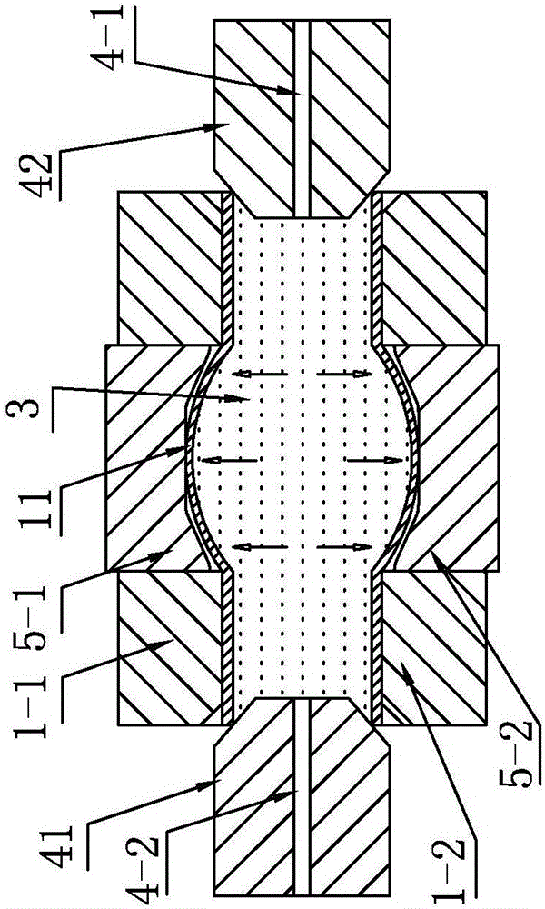
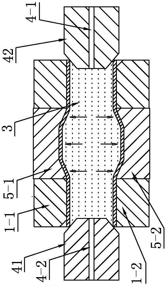
[0042] Specific implementation mode one: combine Figure 1 to Figure 9 Explain that a method of expansion-compression composite forming of large cross-section pipe fittings with different cross-sections in this embodiment is carried out according to the following steps:

[0043] Step 1. Determine the perimeter and equivalent diameter of several cross-sections on the pipe fitting with large cross-section difference and complex special-shaped cross-section to be formed, so as to determine the structure of the expansion-compression composite forming die and the inner cavity size and initial position of the extrusion die; The composite forming die is mainly composed of a bulging die assembled as one and an extrusion die slidingly installed in the bulging die;

[0044] Step 2: Take a tube blank 2 with a certain length and a circular cross-section of equal diameter, put it into the expansion-compression composite forming mold, and clamp the tube blank 2 with a circular cross-section...

specific Embodiment approach 2

[0049] Specific implementation mode two: combination figure 1 , figure 2 , image 3 , Figure 4 as well as Image 6 Note that the difference between this embodiment and the first embodiment is that the expansion-compression composite forming mold in step two is heated to the forming temperature of the equal-diameter circular cross-section tube blank 2 by the heating rod 8 . In this way, the expansion-compression composite forming mold in step 2 has been heated to the forming temperature of the equal-diameter circular-section tube blank 2 before placing the equal-diameter circular-section tube blank 2, the upper mold 1-1 of the bulging mold, and the lower mold of the bulging mold 1-2. The temperature of the upper die 5-1 of the lateral extrusion die and the lower die 5-2 of the lateral extrusion die can be controlled by the heating rod 8 in the heating hole 7. Other steps are the same as in the first embodiment.

specific Embodiment approach 3

[0050] Specific implementation mode three: combination Figure 1-Figure 6 Note, the difference between this embodiment and one of the specific embodiments 1 to 2 is that the sealing left punch 41 and right punch 42 in step 2 are tapered punches or shoulder punches. The beneficial effect of this specific embodiment is: the sealing punch in step 2 can be Figure 1-Figure 4 The tapered punch shown can also be a Figure 5 with Image 6 The shouldered punch 6 is shown. When the tapered punch is used to seal the end of the tube blank, the end of the tube blank is flared and then pressed against the two sides of the mold with the punch to form a rigid seal with good sealing effect and simple operation. It is suitable for applications that do not require bulging The bulging process of zone feeding. The shouldered punch relies on the shoulder and the end of the tube blank to achieve sealing, and at the same time, it will exert an axial force on the end of the equal-diameter circula...


PUM


Abstract

The invention provides a swelling pressure composite forming method for a large-section-difference special-shaped section pipe fitting and relates to a forming method for a large-section-difference special-shaped section pipe-shaped part. The swelling pressure composite forming method comprises the main steps that 1, the perimeters and the equivalent diameters of a plurality of cross sections on the to-be-formed large-section-difference special-shaped section pipe fitting are determined, and the structure of a swelling pressure composite forming mold and the inner cavity size and initial position of a side extrusion mold are determined; 2, an equal-diameter circular-section pipe blank with a certain length is cut and put into the swelling pressure composite forming mold; 3, the equal-diameter circular-section pipe blank is filled with a pressure medium with a certain pressure through a pressure medium inlet, and a variable-diameter circular-section pipe blank is obtained through swelling; 4, the side extrusion mold is driven to extrude the variable-diameter circular-section pipe blank, and the large-section-difference special-shaped section pipe fitting is obtained; and 5, the pressure is released, and after the swelling pressure composite forming mold is opened, the formed pipe fitting is taken out. The swelling pressure composite forming method is used for forming large-section-difference special-shaped section pipe fittings.

Description

technical field [0001] The invention relates to a method for forming a tubular part with a large cross-section and a different cross-section, in particular to an expansion-compression composite forming method for preparing a large cross-section pipe with a different cross-section. Background technique [0002] Tubular parts are a very important class of structural members. In order to obtain ideal structural strength, or to adapt to a specific use space, tubular parts often have complex axes and constantly changing cross-sectional shapes and sizes along the axis. Complex axes can be obtained by bending the original straight tube. In order to obtain continuously changing cross-sectional shape and size along the axial direction, a method of applying higher pressure inside the tube blank to cause the tube blank to bulge is often called hydraulic bulging or internal high pressure forming. [0003] In the process of hydraulic bulging or internal high pressure forming, the secti...

Claims


Application Information

Patent Timeline
Patent Type & Authority Applications(China)
IPC IPC(8): B21D26/047B21C25/02B21C37/15
CPCB21C25/02B21C37/15B21D26/047
Inventor 何祝斌张坤苑世剑
Owner HARBIN INST OF TECH
Learn More