Self-powered pipeline velocity monitor

A monitor, self-powered technology, applied in liquid/fluid solid measurement, instruments, measurement devices, etc., can solve the problems of electromagnetic interference, unsuitable pipelines, and high cost of power generation devices, and achieve uniform stress distribution, controllable deformation, and diameter. small-scale effect

Active Publication Date: 2016-12-07
ZHEJIANG NORMAL UNIVERSITY
View PDF4 Cites 6 Cited by
  • Summary
  • Abstract
  • Description
  • Claims
  • Application Information

AI Technical Summary

Problems solved by technology

Although some of the pipeline leakage or anti-theft monitoring and alarm methods proposed are relatively mature at the technical level, the application of the anti-theft monitoring system for long-distance pipelines in China is still in the preliminary stage and has not been widely used. One of the main reasons is that The power supply problem of the monitoring system has not been well resolved: 1) The method of laying cables is expensive and is easily cut off by criminals, which affects the normal operation of the monitoring system; 2) When using batteries for power supply, the use time is limited and needs to be replaced frequently. Once the battery is insufficient and not replaced in time, the remote transmission of monitoring information cannot be completed; 3) In recent years, in order to meet the self-power supply requirements of related wireless sensor monitoring systems, people have also proposed various forms of turbine-type miniature power generation devices. The biggest problem is that the structure is complex and the volume is relatively large, which is not suitable for occasions with small diameter pipes. Some structures of power generation devices also have electromagnetic interference and other phenomena, and their popularization and application have been restricted to a certain extent.

Method used


Image

  • Self-powered pipeline velocity monitor
  • Self-powered pipeline velocity monitor
  • Self-powered pipeline velocity monitor

Examples


Embodiment Construction

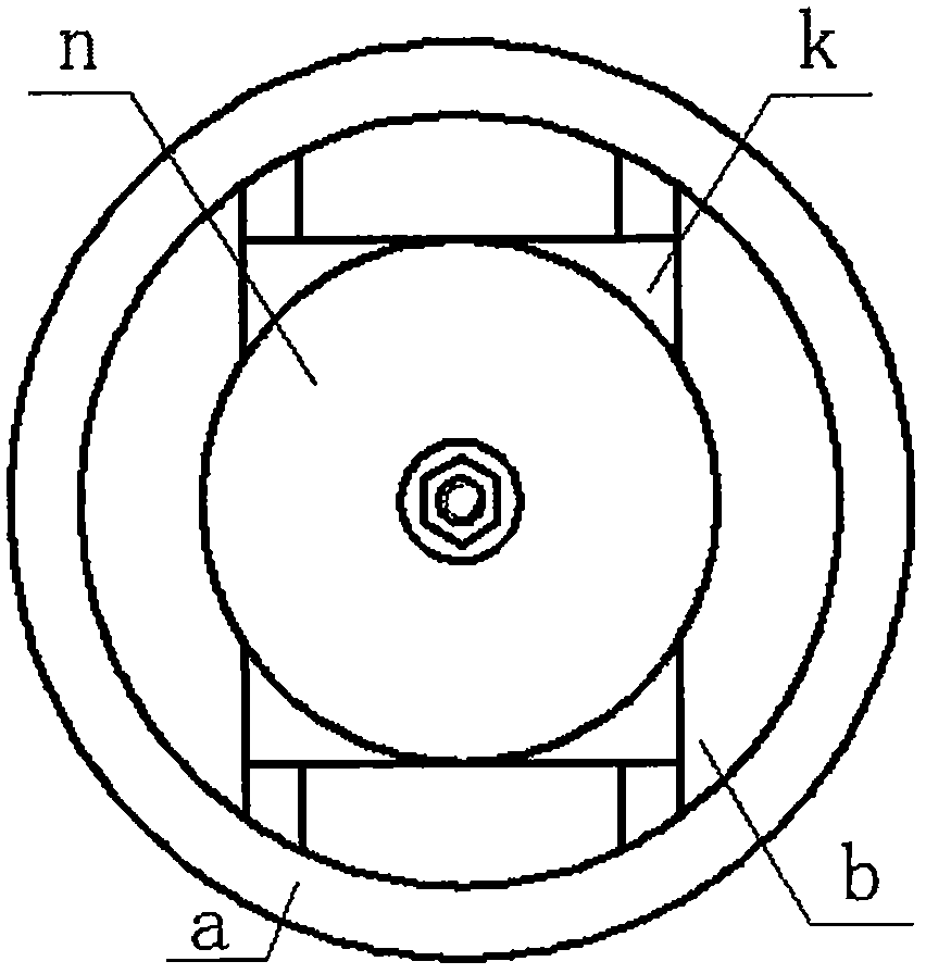
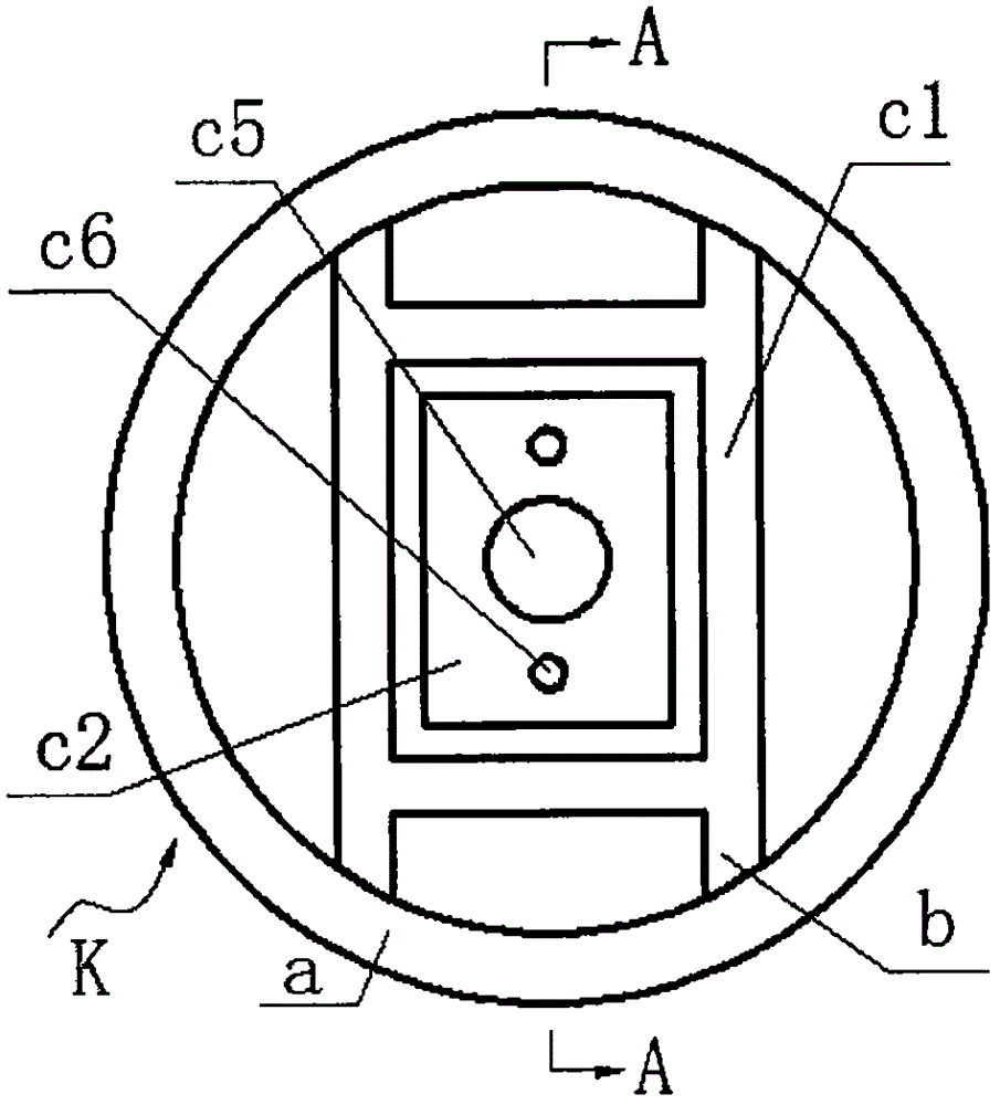
[0014] The inner cylinder c is fixed on the inner wall of the pipeline a through the rib plate b, and the pipeline a, rib b and inner cylinder c form the main frame K; the partition c2 provided with the guide hole c5 and the wire hole c6 separates the inner cylinder c into left Cavity c3 and right cavity c4, the inside of the left cavity c3 is installed with a circuit board d with a transmitting unit P through screws, and the end is installed with a left end cover k through screws: the left semi-axis m1 of the stepped axis m passes through the center hole of the left end cover k from The left chamber c3 protrudes, and the end of the left half shaft m1 is equipped with an actuator n; the left half shaft m1 is covered with a balance spring j1 and a limit spring j2, and the left and right ends of the balance spring j1 respectively lean against the exciter n and the left end cover On k, the left and right ends of the limit spring j2 respectively lean against the left end cover k an...


PUM


Abstract

The invention relates to a self-powered pipeline velocity monitor and belongs to the technical field of fluid monitoring. An inner cylinder of the pipeline is separated in to a left chamber and a right chamber by a separator plate, wherein end parts of the left chamber and the right chamber are both provided with end covers; the left chamber is provided with a circuit board; an end part of a left half shaft of a stepped shaft is provided with an exciter and is sleeved by a balancing spring and a spacing spring and the left half shaft of the stepped shaft extends out through the left end cover; a right half shaft extends to the right chamber loaded with energy transducers through the separator plate; a piezoelectric vibrator is formed by a metal substrate and a bonded piezoelectric wafer; each energy transducer is formed by two piezoelectric vibrators and N-shaped framework structures installed at two ends of the piezoelectric vibrators; piezoelectric vibrators at two sides inside the right chamber are respectively connected with the right end cover and a crash pad on the right half shaft; adjacent piezoelectric vibrators of different energy transducers are connected through a separator pad. The self-powered pipeline velocity monitor has following advantages: power generation and flow velocity self-measurement can be fulfilled through a fluid-solid coupling effect so that flow velocity online monitoring can be realized; the monitor is configured along the length of the pipeline, the structure is simple, the radial scale is small, and it is easy to get required energy through the multiple piezoelectric vibrators; the piezoelectric vibrators have reasonable structure, large generated energy amount and high reliability.

Description

technical field [0001] The invention belongs to the technical field of pipeline fluid monitoring, and in particular relates to a self-powered pipeline flow velocity monitor. Background technique [0002] Due to natural corrosion, natural force majeure, and man-made theft, leakage events of long-distance pipelines for oil and natural gas and other fluids during use occur from time to time. Frequent pipeline leakage not only causes huge economic losses, but also affects the surrounding nature. The environment has caused serious pollution. In the past, regular manual inspections were often used for maintenance. However, due to the long laying distance of oil and gas pipelines and the fact that they are often located in inaccessible or inconvenient places, regular inspections are difficult to find leaks and maintain them in time. Therefore, various types have been proposed for pipeline leakage monitoring or anti-theft systems. Although some of the pipeline leakage or anti-thef...

Claims


Application Information

Patent Timeline
IPC IPC(8): G01F1/64
CPCG01F1/64
Inventor 温建明王淑云程光明王鸿云阚君武
Owner ZHEJIANG NORMAL UNIVERSITY
Why Eureka
Try Eureka