Lead alloy anode plate for electrochemical metallurgy and manufacturing method of lead alloy anode plate

A lead alloy and anode plate technology, applied in the direction of electrodes, electrolysis process, electrolysis components, etc., can solve problems such as segregation, uneven distribution, coarse grains, etc., and achieve the effects of prolonging service life, reducing corrosion rate, and small size

Active Publication Date: 2016-12-07
有研资源环境技术研究院(北京)有限公司
View PDF8 Cites 3 Cited by
  • Summary
  • Abstract
  • Description
  • Claims
  • Application Information

AI Technical Summary

Problems solved by technology

Although this anode material reduces the surface defects of the cast lead alloy anode material and improves the mechanical strength of the anode material, it still has the shortcoming that the service life of the lead alloy anode plate is too short
In addition to the factors of electrolytic environment, the main reasons for the short service life of lead alloy anode plates are: (1) the second phase formed by doping elements is unevenly distributed in the matrix, and defects such as segregation appear; The lead alloy anode plate prepared by rolling the alloy ingot with a small reduction (the total reduction is less than 60%) has casting defects such as coarse grains; (3) the alloy ingot after complete cooling is subjected to a large reduction ( The total reduction is greater than 70%), the lead alloy anode plate prepared by rolling has a large number of dislocation defects in its structure, the grain size distribution is extremely uneven, and creep is prone to occur during the electrolysis process

Method used


Image

  • Lead alloy anode plate for electrochemical metallurgy and manufacturing method of lead alloy anode plate
  • Lead alloy anode plate for electrochemical metallurgy and manufacturing method of lead alloy anode plate
  • Lead alloy anode plate for electrochemical metallurgy and manufacturing method of lead alloy anode plate

Examples


Embodiment 1

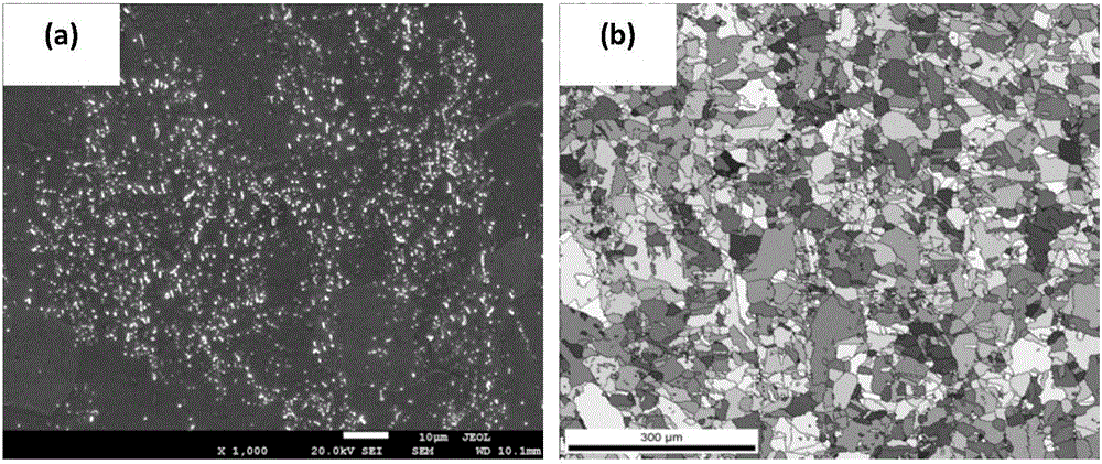
[0025] The chemical composition is: silver 0.85wt%, and the rest is lead alloy liquid into a water-cooled iron mold with a specification of 600×480×60mm, and the surface layer of the alloy liquid in the water-cooled iron mold is completely solidified, and the temperature in the center of the surface layer is cooled to Demould at 220°C to obtain semi-solidified lead alloy ingots; then use a twin-roll mill to reduce the amount of passes by 60→54→48→42→36→30→26→22→18→14→10→8, The semi-solidified lead alloy ingot is pressed down multiple times to obtain a lead-silver alloy anode plate with a size of 450×580×8mm, and its surface appearance is as follows: figure 1 As shown in -a, the OIM diagram is as follows figure 1 -b shown.

[0026] Depend on figure 1 -a It can be seen that, compared with the lead-silver alloy anode plate prepared by the conventional process, the silver-rich phase of the lead-silver alloy anode plate prepared by this method is dispersedly distributed on the su...

Embodiment 2

[0029] The chemical composition is: silver 0.20wt%, calcium 0.08wt%, strontium 0.05wt%, and the rest is lead alloy liquid into a water-cooled iron mold with a specification of 600×480×60mm, and the alloy liquid in the water-cooled iron mold is The surface layer is completely solidified, and the temperature of the central area of ​​the surface layer is cooled to 180°C, and the mold is demoulded to obtain a semi-solidified lead alloy ingot; then use a two-roll mill to press 60→54→48→43→38→34→30→26→22→18→ 14 → 11 → 8 → 7 → 6 pass reduction, the semi-solidified lead alloy ingot is subjected to multi-pass reduction to obtain a lead-silver-calcium-strontium alloy anode plate with a size of 450×580×6 mm.

[0030] The electrochemical performance of the lead-silver-calcium-strontium alloy anode plate prepared by this method in the zinc electrowinning process was detected, and the detection process conditions were as described in Example 1; the detection results are shown in Table 1.

Embodiment 3

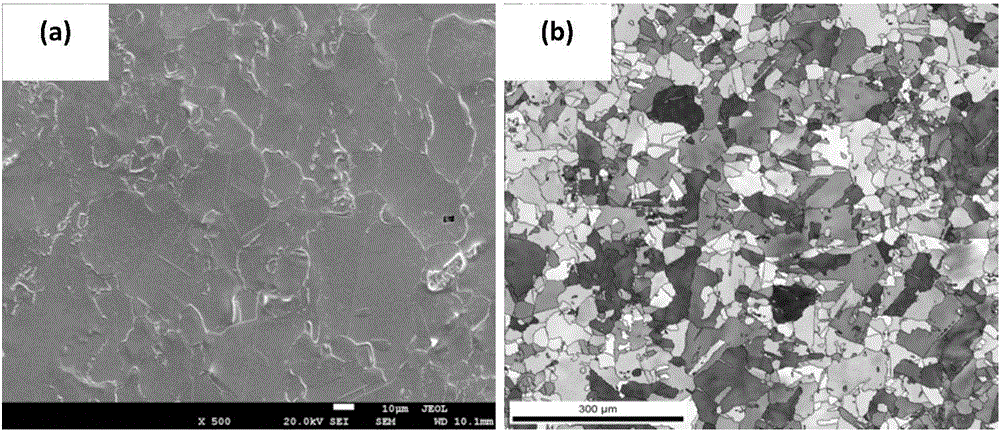
[0037] The chemical composition is: 0.08wt% of calcium, 1.70wt% of tin, 0.005wt% of aluminum, and the rest is lead. The surface layer is completely solidified, and when the temperature of the central area of ​​the surface layer is cooled to 150°C, the mold is demoulded to obtain a semi-solidified lead alloy ingot; 14 → 10 → 8 pass reduction, multi-pass reduction of semi-solidified lead alloy ingot to obtain a lead-calcium-tin-aluminum alloy anode plate with a size of 450×580×8mm, and its surface appearance is as follows image 3 As shown in -a, the OIM diagram is as follows image 3 -b shown.

[0038] Depend on image 3 -a It can be seen that, compared with the lead-calcium-tin-aluminum alloy anode plate prepared by the conventional process, there are a large number of deformation twins on the surface of the lead-calcium-tin-aluminum alloy anode plate prepared by this method. Depend on image 3 -b It can be seen that the surface of the lead-calcium-tin-aluminum alloy anode...


PUM

PropertyMeasurementUnit
Average grain sizeaaaaaaaaaa

Abstract

The invention discloses a lead alloy anode plate for electrochemical metallurgy and a manufacturing method of the lead alloy anode plate, and belongs to the technical field of electrochemical metallurgy. Alloy liquid is injected into a water-cooling iron mold; demolding is carried out when the surface layer of the alloy liquid in the water-cooling iron mold is completely solidified, and a semi-solidified lead alloy ingot is obtained; and then a dual-roller rolling mill is used for carrying out multi-pass reduction on the semi-solidified lead alloy ingot, the total reduction is not lower than 70%, and the lead alloy anode plate with the thickness being 6-8 mm is obtained. The prepared lead alloy anode plate is of a crystal structure that the grain orientation is random, dimension is fine, and the quantity of special grain boundaries is large; the texture is fine and uniform, and the number of defects and gross segregation is remarkably reduced; and when the anode plate is applied to non-ferrous metal electrodeposition, the corrosion rate of the anode plate can be remarkably reduced, and the service life of the anode plate is prolonged to a great extent.

Description

technical field [0001] The invention belongs to the technical field of electrochemical metallurgy, and in particular relates to a lead alloy anode plate for electrochemical metallurgy and a preparation method thereof. Background technique [0002] When electrowinning non-ferrous metals such as zinc, copper and manganese, lead alloys are usually used as anode materials. In all anodes for electrochemical metallurgy, the doping element calcium can improve the strength of the lead alloy anode, but its content must be strictly controlled below 0.15%, otherwise the service life of the anode will be shortened. In the anode for electrowinning zinc, the doping element silver can reduce the oxygen evolution overpotential and corrosion rate of lead in the electrowinning process, so as to achieve the purpose of reducing power consumption and prolonging the service life of the anode; the effect of doping element strontium is to reduce lead The corrosion rate in the electrowinning proces...

Claims


Application Information

Patent Timeline
IPC IPC(8): C25C7/02C22C11/00C22C11/06C22C11/02C22F1/12B22D25/04
CPCB22D25/04C22C11/00C22C11/02C22C11/06C22F1/12C25C7/02
Inventor 袁学韬华志强车小奎王磊吕旭东
Owner 有研资源环境技术研究院(北京)有限公司
Why Eureka
Try Eureka