Electric current assisted friction column/tapered plug welding method and tool thereof

A plug welding and current technology, applied in welding equipment, non-electric welding equipment, manufacturing tools, etc., can solve the problems of fast welding cooling speed, insufficient friction heat source, welding machine stuck, etc., to reduce process requirements, broad development prospects, Additional Equipment Simple Effects

Inactive Publication Date: 2016-12-07
TIANJIN UNIV
View PDF8 Cites 8 Cited by
  • Summary
  • Abstract
  • Description
  • Claims
  • Application Information

AI Technical Summary

Problems solved by technology

[0005] There are some problems in the application process of traditional friction column / cone plug welding: (1) high requirements on welding equipment, high welding speed and large axial pressure are required, resulting in a narrow range of welding process adjustment; (2) At the beginning of welding, due to the excessive load, the welding torque rises rapidly, which may easily cause the welding machine to be stuck due to overload; (3) the flow of plastic material at the fillet transition at the bottom of the plug weld is not sufficient, and due to insufficient frictional heat source, it is easy to cause unwelded (4) Due to the short duration of the welding process and the fast welding cooling rate, a coarse structure may be formed inside the entire plug weld, resulting in an increase in hardness and a decrease in plasticity, which has an adverse effect on the mechanical properties and plastic deformation of the plug weld

Method used


Image

  • Electric current assisted friction column/tapered plug welding method and tool thereof
  • Electric current assisted friction column/tapered plug welding method and tool thereof

Examples


Embodiment Construction

[0023] The technical solution of the present invention will be further described in detail below in conjunction with the accompanying drawings and specific embodiments, and the described specific embodiments are only for explaining the present invention, and are not intended to limit the present invention.

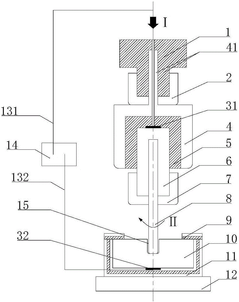
[0024] The design concept of the present invention is to pass current into the welding zone of the workpiece and generate resistance heat at the friction interface where the stopper rod contacts the plug hole of the workpiece, and the resistance heat and friction heat form a composite heat source in the friction column / cone plug welding process, Thus, the current-assisted friction column / taper plug welding process is realized. The main measures to realize resistance heat generation are: connect one electrode of the auxiliary power supply to the upper conductive block in contact with the stopper through a cable, and connect the other electrode of the auxiliary power supply t...


PUM


Abstract

The invention discloses an electric current assisted friction column / tapered plug welding method which comprises the following steps: according to the technological requirements of friction plug welding, a cylindrical or frustum-shaped stopper rod is adopted to prefabricate a taphole in the to-be-welded area of a workpiece; a tool is utilized to clamp the stopper rod and the workpiece, and the taphole and the stopper rod are enabled to be coaxial; a welding machine and an auxiliary power supply are started, axial force is applied while rotating the stopper rod to form a conductive loop among the auxiliary power supply, the stopper rod, the workpiece and a conductive block, the end material of the stopper rod rapidly reaches the thermoplasticity state under the action of friction heat and resistance heat, and at the same time, a plastic material moves around to fill an interval under the action of thermal mechanical coupling, and the interval is filled as the welding process is carried out; and after upsetting is finished, the welding machine and the auxiliary power supply are turned off, so that electric current assisted friction column / tapered plug welding is finished. With adoption of the electric current assisted friction column / tapered plug welding method, requirements for friction heat can be lowered, so that requirements for the power system of welding equipment are lowered, plug weld texture and mechanical properties can be improved, and a welding process window can be widened.

Description

technical field [0001] The invention belongs to the technical field of solid-phase friction welding, and in particular relates to a novel friction column / cone plug welding method using a composite heat source of electric current and solid-phase friction. Background technique [0002] Friction column / plug welding is a new type of solid-phase joining technology based on the welding process of continuous drive friction welding and stud welding. It was invented and patented by the British Welding Institute in 1992. The basic principle is: prefabricate a plug hole to be welded on the base metal, keep the consumable plug rod material with a diameter smaller than the plug hole concentric with the plug hole, and rotate at a high speed, while exerting a certain axial pressure on the plug rod and The bottom of the plug hole moves, and when the rotating stopper rod comes into contact with the bottom of the plug hole, the heat generation process of frictional shearing begins. Under the...

Claims


Application Information

Patent Timeline
Patent Type & Authority Applications(China)
IPC IPC(8): B23K20/12B23K20/26
CPCB23K20/122B23K20/1245B23K20/126B23K20/26
Inventor 林伟杨新岐
Owner TIANJIN UNIV
Why Eureka
Try Eureka