A method and system for separating shear waves propagating in a crack
A separation method and separation system technology are applied in the separation field of shear waves propagating in cracks, which can solve the problems of low accuracy of shear waves propagating in cracks, and achieve the effects of high accuracy and simple analysis and operation process.
- Summary
- Abstract
- Description
- Claims
- Application Information
AI Technical Summary
Problems solved by technology
Method used
Image
Examples
Embodiment 1
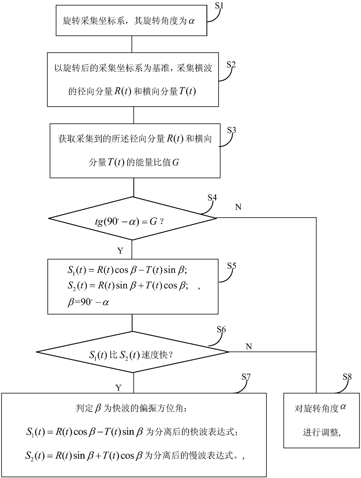
[0055] This embodiment provides a method for separating shear waves propagating in cracks, such as figure 1 shown, including the following steps:
[0056] S 1 : Rotate the acquisition coordinate system, the rotation angle is α, and the rotation angle is based on the counterclockwise direction. In this step, there is no specific requirement for the rotation direction of the acquisition coordinate system, but the final rotation angle is based on the counterclockwise direction. For example, it can be rotated 240° clockwise, and the final rotation angle is 120° counterclockwise. Then the rotation angle is 120°. As another measurement method, it can be considered that the clockwise rotation angle is negative and the counterclockwise rotation angle is positive. For example, if the clockwise rotation is 30°, it can be considered as -30° counterclockwise rotation.
[0057] S2: Based on the rotated collection coordinate system, collect the radial component R(t) and transverse compo...
Embodiment 2
[0091] This embodiment provides a shear wave separation system propagating in a crack, such as Image 6 shown, including:
[0092] Rotation unit 1, which rotates the acquisition coordinate system, and its rotation angle is the angle α in the counterclockwise direction;
[0093] Acquisition unit 2, based on the rotated acquisition coordinate system, acquires the radial component R(t) and transverse component T(t) of the shear wave, where t is the propagation time of the shear wave in the crack;
[0094] A data acquisition unit 3, which acquires the energy ratio G of the collected radial component R(t) and transverse component T(t);
[0095] The first judging unit 4 judges whether the rotation angle α satisfies tg(90°-α)=R;
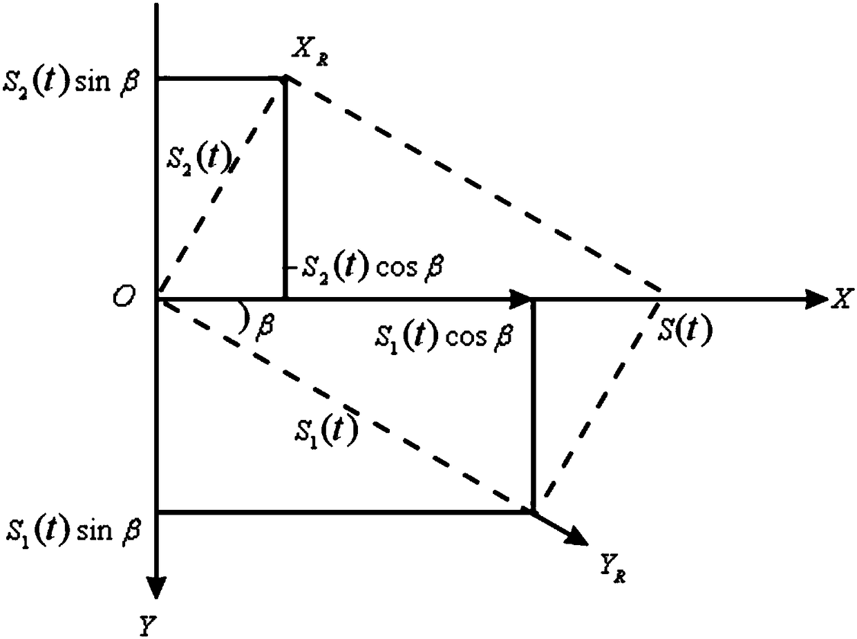
[0096] The processing unit 5, when the determination result of the determination unit 4 is yes, acquires the fast wave component S 1 (t) and the slow wave component S 2 Expression of (t): S 1 (t)=R(t)cosβ-T(t)sinβ; S 2 (t)=R(t) sinβ+T(t)cosβ; where, β...
Embodiment 3
[0104] This embodiment provides an identification mark for the orientation of coal seam fissures. In order to establish the change relationship between the coal seam conversion wave field and the coal seam fissures, a forward modeling simulation is performed on the coal seam fissure model. Coal seam geological model such as Figure 7 As shown, all the strata are horizontally layered, and the coal seam fractures are vertical fractures parallel to each other, and the direction is parallel to the Y axis. The parameters corresponding to each layer are shown in Table 1.
[0105] Table 1 Physical property parameters of coal seam geological model
[0106]
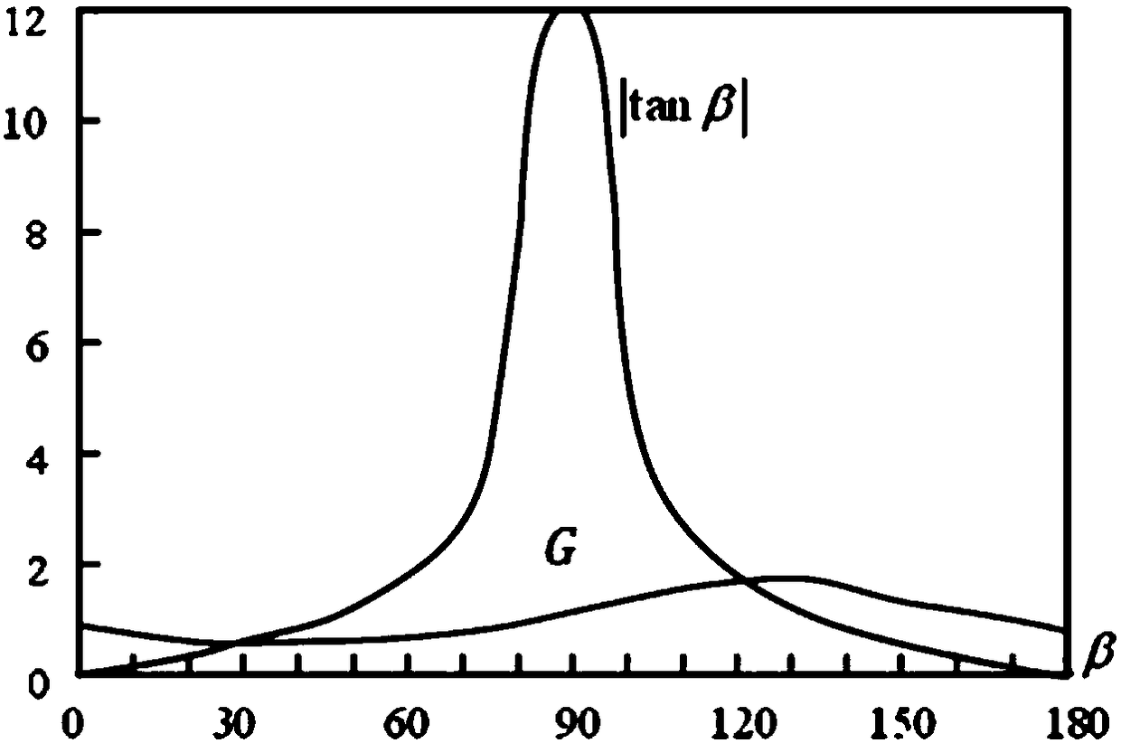
[0107] Excited at point O, received on a circular survey line with point O as the center and radius r (r=1400m in the model), the azimuth angle θ of the crack is calculated from the X axis (that is, the direction of true north), and the model is calculated using the reflectivity method The wave field of , the subwave is select...
PUM
 Abstract
Description
Claims
Application Information
 - R&D Engineer
- R&D Manager
- IP Professional
- Industry Leading Data Capabilities
- Powerful AI technology
- Patent DNA Extraction
Browse by: Latest US Patents, China's latest patents, Technical Efficacy Thesaurus, Application Domain, Technology Topic, Popular Technical Reports.
© 2024 PatSnap. All rights reserved.Legal|Privacy policy|Modern Slavery Act Transparency Statement|Sitemap|About US| Contact US: help@patsnap.com


