Coupling dual-drive microfluidic chip device for simultaneously detecting various subtype swine influenzas

A microfluidic chip and swine flu technology, applied in the field of analysis and testing, can solve the problems of microchannel bubbling substrate and cover sheet, PDMS microchannel inner surface modification operation trouble, large flow resistance, etc.

Inactive Publication Date: 2016-11-23
NINGBO UNIV
View PDF5 Cites 1 Cited by
  • Summary
  • Abstract
  • Description
  • Claims
  • Application Information

AI Technical Summary

Problems solved by technology

[0007] But it's not that simple
[0008] First, this polydimethylsiloxane material, the material referred to by the acronym PDMS, is itself a strongly hydrophobic material. Microchannels are built on this material. If the microchannels are not targeted The modification operation of the surface of the channel, then, after the overall assembly is completed, that is, after the cover is covered, because the inner surface of the micro channel in the structure occupies most of the inner surface of the liquid flow channel, then the PDMS micro channel The strong hydrophobic characteristic of the inner surface of the channel is the decisive factor, which will make it very difficult for the polar liquid flow similar to the aqueous solution to pass through, and its flow resistance is so large that even ordinary micropumps are difficult to push. Of course, If the cover sheet also chooses to use the PDMS material, then the problem is basically the same, with little difference; therefore, in the prior art, it is necessary to modify and modify the inner surface of the microchannel on the PDMS material; then , is this modification operation for the inner surface of the PDMS microchannel very troublesome? That's not the problem. What constitutes a serious technical problem is another problem: the PDMS polymer molecules in the bulk phase of the PDMS material substrate have the characteristics of automatic diffusion and migration to the surface. The characteristics of polymer molecules diffusing and migrating to the surface automatically will make the modified state of the inner surface of the microchannel modified by the surface modification unable to maintain for a long enough time, and the microgroove after surface modification The maintenance time of the inner surface state of the channel is roughly only enough to complete the time required for the internal test experiment in the laboratory; in other words, the inner surface of the PDMS microchannel after surface modification or surface modification is formed after modification The surface state of the surface does not last long, but quickly tends to or changes back to the surface state before the surface modification, and returns to the original strongly hydrophobic surface state in a relatively short period of time. Then, just imagine, Can such microfluidic chips be produced in large quantities, stored in large quantities, and widely promoted? The answer is obvious, that is, impossible
[0016] Third, as mentioned above, the inner surface of the PDMS microchannel is strongly hydrophobic, and targeted surface chemical modification or surface chemical modification is difficult to last. It is effective to use it within a short period of time; if the relatively short expiration date has passed and it is still used forcibly, since the surface state is already close to the hydrophobic state, there must be a comparison between using the conventional micropump to drive the sample liquid flow. Large flow resistance, in this way, the sample liquid can only be forced to flow in the target direction by increasing the pumping power and pumping pressure of the micropump. Pumping pressure to pump the sample liquid flow will cause bubbling, puffing, twisting, and deformation of the microchannels at the sampling end of the substrate including the area near the sampling end, and, under such high pressure conditions, The microgroove and its periphery at the sample inlet and its vicinity are also prone to peeling between the substrate and the cover slip. In this case, the sample solution will enter between the substrate and the cover slip formed after the peeling. This actually leads to the damage of the microfluidic chip; of course, if the surface modification or the surface modification is not in place, it will also lead to the above-mentioned situation within the short customary validity period; In the case of simply using an external micropump for liquid flow drive, the above-mentioned problem always exists
As mentioned above, if no pre-operations such as surface modification or surface modification have been done at all, then the above-mentioned problem will be more serious, even if the microchannel bubbling at the injection end and its vicinity does not occur , puffing, twisting, deformation, and peeling between the substrate and the cover sheet, etc., just because the flow resistance is too large, the use of a high-pressure micropump may not be able to drive the sample liquid flow toward the terminal.

Method used


Image

  • Coupling dual-drive microfluidic chip device for simultaneously detecting various subtype swine influenzas

Examples


Embodiment Construction

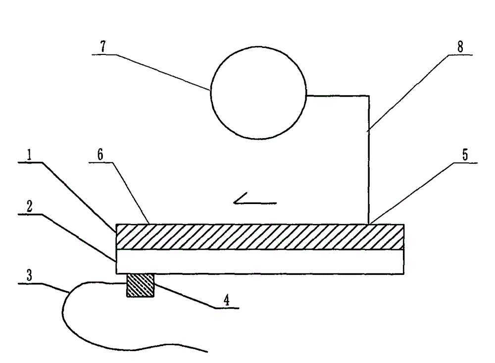
[0051] in figure 1 In the embodiment shown in the present case, the structure of the device includes a multi-channel microfluidic chip. The structure of the microfluidic chip includes a substrate 1 and a cover sheet 2 that are attached to each other and mounted together. The substrate 1 Both the cover sheet 2 and the cover sheet 2 are plate-like or sheet-like objects, and the surface of the substrate 1 facing the cover sheet 2 contains a channel structure formed by a molding process or an etching process, and the base sheet is attached to each other and mounted together. The sheet 1 and the cover sheet 2 are jointly constructed to form a microfluidic chip containing a pipe structure. The structure of the pipe is located at the junction area where the substrate 1 and the cover sheet 2 are attached to each other. The sampling end 5 of the microfluidic chip is connected to the terminal 6. The sampling end 5 is the injection end of the sample solution of the microfluidic chip, and ...


PUM

PropertyMeasurementUnit
diameteraaaaaaaaaa
lengthaaaaaaaaaa
thicknessaaaaaaaaaa

Abstract

The invention relates to a coupling dual-drive microfluidic chip device for simultaneously detecting various subtype swine influenzas and belongs to the field of analytical testing. Cheap polydimethylsiloxane very easy to treat, namely PDMS, is used for making a substrate of a microfluidic chip for subtype swine influenza diagnosis, and a series of problems exist actually. According to the key point of the scheme for solving the problems, the substrate is prepared by selecting the PDMS having an original ecological surface, a miniature ultrasonic transducer is fixedly installed at the neighbor position of the sample liquid flow end of the microfluidic chip, interfacial tension is reduced by using ultrasonic waves, meanwhile rapid progressive decrease of the ultrasonic intensity within a short distance is achieved by utilizing the strong ultrasonic wave absorption capability of the PDMS, accordingly interfacial tension difference is formed at two ends of the chip and provides the strength forcing sample liquid flow towards the end direction along a lyophobic capillary channel, and meanwhile the strength mutually supports, couples and adjusts and collaboratively operates with the mechanical pumping strength of a micro pump included in the structure.

Description

Technical field [0001] The invention relates to a microfluidic chip device for simultaneous detection of multiple subtypes of swine flu with coupled dual drives. The microfluidic chip device is a special device for diagnosing subtypes of swine flu antigens based on antigen / antibody specific reactions, and belongs to analysis Test area. Background technique [0002] For the technical background of multi-channel microfluidic subtype swine flu diagnosis, please refer to CN 201110311127.1 and other invention patent applications. [0003] For the overall overview of microfluidic technology itself, you can refer to the monograph "Illustrated Microfluidic Chip Laboratory" recently published by the famous microfluidic expert Mr. Lin Bingcheng. This monograph has been published by Science Press. The past, present, and future prospects of microfluidic technology are all detailed and detailed long discussions. [0004] So, let's talk about the key issues of concern in this case. [0005] The b...

Claims


Application Information

Patent Timeline
Patent Type & Authority Applications(China)
IPC IPC(8): G01N27/416G01N33/543B01L3/00
Inventor 李榕生干宁冯小彬李天华何佳丽朱云云缪养宝
Owner NINGBO UNIV
Why Eureka
Try Eureka