Oil Pressure Control Device

A technology of oil pressure control and equipment, which is applied in the direction of mechanical equipment, transmission device control, fluid pressure actuation device, etc., and can solve the problem of slow reciprocating cycle of the valve core

Inactive Publication Date: 2016-11-23
DENSO CORP
View PDF7 Cites 0 Cited by
  • Summary
  • Abstract
  • Description
  • Claims
  • Application Information

AI Technical Summary

Problems solved by technology

[0003] However, the reciprocating cycle of the spool in the o

Method used


Image

  • Oil Pressure Control Device
  • Oil Pressure Control Device
  • Oil Pressure Control Device

Examples


Embodiment Construction

[0020] An embodiment will be described below with reference to the drawings.

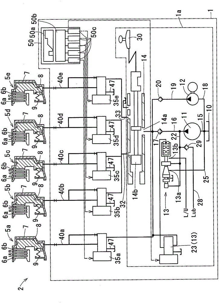
[0021] The vehicle's automatic shift 2 has figure 1 Oil pressure control device 1 shown. The oil pressure control device 1 controls the friction elements 5a-5e of the automatic shift 2 by controlling the supply pressure supplied to the friction elements 5a-5e. Vehicles with Autoshift 2 employ an idle stop system to suspend the internal combustion engine (not shown) when the shift position is in the forward drive range and when the vehicle's speed is below a predetermined value.

[0022] Automatic shifting 2 is a step-by-step transmission including a torque converter (not shown) connected to a crankshaft (not shown) of an internal combustion engine, a planetary gear transmission (not shown), friction elements 5a-5e and oil Pressure control device 1. The transmission mechanism has planetary gears (not shown). The friction elements 5a-5e transmit the torque of a rotating element such as a planetary...


PUM


Abstract

An oil pressure control device controls the supply pressure of oil supplied to an oil pressure chamber of a friction element having a first engagement board 6a and a second engagement board 6b engaged with or disengaged from each other between a non-engagement state and a non-sliding engagement state via a sliding engagement state. The oil pressure control device includes: an electromagnetic valve that controls the supply pressure using a spool 44 which reciprocates according to an energizing amount; and a control part 52 that defines a first oscillatory wave part in which the energizing amount is controlled by making a first waveform with a first frequency to superimpose on a second waveform with a second frequency higher than the first frequency during a first period while the sliding engagement state and an instruction value of the supply pressure are kept constant.

Description

technical field [0001] The present disclosure relates to an oil pressure control device. Background technique [0002] Foreign substances such as metal powder may be mixed in the working oil that transmits the supply pressure to the automatic shift of the vehicle. If foreign matter enters the gap between the spool of the solenoid valve and the valve sleeve that receives the spool to slide, the foreign matter affects the operation of the spool. JP H11-82724A (USP5971889) describes an oil pressure control device in which foreign matter is removed by a reciprocating spool. [0003] However, the reciprocating cycle of the spool in the oil pressure control device is very slow, such as three seconds. With the spool operating at such a low frequency with the spool having a reciprocating amplitude sufficient to dislodge foreign matter, the supply pressure may be varied by the movement of the spool. Considering the shift shock (vibration), the removal of foreign substances may not...

Claims


Application Information

Patent Timeline
IPC IPC(8): F16H61/06
CPCF16H61/061F15B13/044F15B21/041F15B2211/3059F15B2211/328F15B2211/655F16H61/0276F15B13/0402F16H2061/0043F16H2061/0279F15B15/14
Inventor 酒井阳铃木文规
Owner DENSO CORP
Why Eureka
Try Eureka