Metalworking cutting machine tool facilitating position adjustment
A technology of metal processing and cutting machine tools, which is applied to metal processing machinery parts, metal processing equipment, shearing devices, etc., and can solve problems such as tool damage
- Summary
- Abstract
- Description
- Claims
- Application Information
AI Technical Summary
Problems solved by technology
Method used
Image

Examples
Embodiment 1
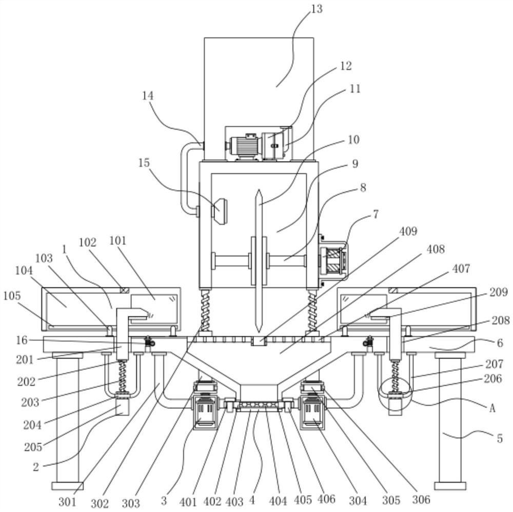
[0042] Example 1: See Figure 1-8 , a metal processing and cutting machine tool for easy position adjustment, comprising legs 5 and a workbench 6, four corners at the bottom of the workbench 6 are respectively fixedly connected with a group of legs 5, and the top of the workbench 6 is provided with a top frame 9, One side of the top frame 9 is fixedly connected with a drive motor 7, the model of the drive motor 7 is Y90L-4, the output end of the drive motor 7 runs through one side of the top frame 9 and extends to the inside of the top frame 9, and is fixedly connected with a rotating shaft 8 , the rotating shaft 8 is movably connected with the top frame 9, the outside of the rotating shaft 8 is fixedly connected with a cutting knife 10, the bottom end of the top frame 9 is provided with a lifting mechanism 3, the top of the workbench 6 is provided with a protective structure 1, and the bottom end of the workbench 6 A positioning structure 2 is provided, a collection structure...
Embodiment 2
[0046] see Figure 1-8 , the cooling mechanism includes a water pump 12, the water pump 12 is fixedly connected to the top of the top frame 9, the model of the water pump 12 is JET-1100, the top of the top frame 9 is fixedly connected to the water tank 13, and the input end of the water pump 12 is fixedly connected to the suction pipe 11 , the suction pipe 11 runs through the bottom of the water tank 13 and communicates with the inside of the water tank 13, the output end of the water pump 12 is fixedly connected with a water outlet pipe 14, and the water outlet pipe 14 runs through one side of the top frame 9 and extends to the inside of the top frame 9 for fixing connected to the spout 15;
[0047] The length of water tank 13 is less than the length of top frame 9, and the width of spout 15 is less than the width of top frame 9 inside;
[0048] Specifically, as figure 1 As shown, when using this device to cut the metal plate, start the drive motor 7 to drive the rotating s...
Embodiment 3
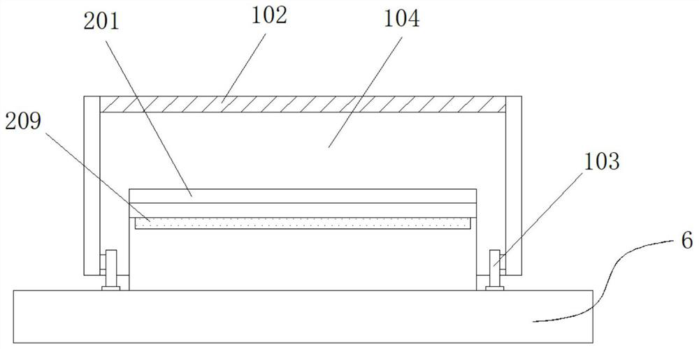
[0049] Embodiment 3: protective structure 1 is made up of window 101, buffer pad 102, positioning block 103, protective cover 104 and chute 105, protective cover 104 is arranged on the both sides of workbench 6 top, and the bottom end of protective cover 104 inner two ends is respectively A set of chute 105 is inlaid, and a set of positioning blocks 103 are movably connected to both sides of the chute 105, and the positioning block 103 is fixedly connected with the workbench 6. A set of windows 101 and a protective cover 104 are inlaid on the same side of the two ends of the protective cover 104 respectively. One side of the top is fixedly connected with a buffer pad 102, and the buffer pad 102 is movably connected with the top frame 9;
[0050] The width inside the protective cover 104 is greater than the width of the top frame 9, and the width of the buffer pad 102 is equal to the width inside the protective cover 104;
[0051] Specifically, as figure 1 and figure 2 As sh...
PUM
 Abstract
Description
Claims
Application Information
 - R&D
- Intellectual Property
- Life Sciences
- Materials
- Tech Scout
- Unparalleled Data Quality
- Higher Quality Content
- 60% Fewer Hallucinations
Browse by: Latest US Patents, China's latest patents, Technical Efficacy Thesaurus, Application Domain, Technology Topic, Popular Technical Reports.
© 2025 PatSnap. All rights reserved.Legal|Privacy policy|Modern Slavery Act Transparency Statement|Sitemap|About US| Contact US: help@patsnap.com