
Method For Detecting Leaks In Intake Manifold

An intake manifold and intake valve technology, which is applied in electrical control, engine starting, engine motor starting, etc., can solve problems such as reduced efficiency, complicated leakage diagnosis, and time-consuming

Pending Publication Date: 2016-11-23
FORD GLOBAL TECH LLC
View PDF5 Cites 12 Cited by
  • Summary
  • Abstract
  • Description
  • Claims
  • Application Information

AI Technical Summary

Problems solved by technology

Here, leak diagnosis can be more complex, time-consuming and with reduced efficiency

Method used


Image

  • Method For Detecting Leaks In Intake Manifold
  • Method For Detecting Leaks In Intake Manifold
  • Method For Detecting Leaks In Intake Manifold

Examples


Embodiment Construction

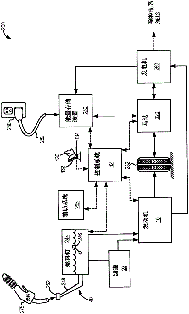
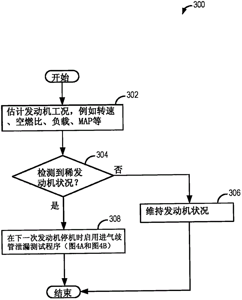
[0016] The following description refers to methods used to determine whether an engine system such as figure 1 Systems and methods for leaks in an intake manifold of an example engine system). The engine system may be a hybrid vehicle propulsion system such as figure 2 part of the hybrid vehicle system). The leak test may be initiated in the engine in response to detecting a lean engine condition in the engine ( image 3 ). Thus, leak testing may include, by closing the intake throttle and terminating airflow from other sources, when the engine is shut down to rest ( Figure 4A , Figure 4B ) creates a vacuum in the intake manifold. All intake valves of all cylinders of the engine may be fully closed in response to vacuum in the intake manifold reaching a predetermined level. In camless engines, the intake valve may be adjusted closed via an electromechanical actuator. In a hybrid vehicle, the intake valve is regulated to close ( Figure 5 ). Alternative methods of i...


PUM


Abstract

The present invention relates to a method for detecting leaks in an intake manifold. Methods and systems are provided for detecting leaks in the intake manifold of an engine. In one example, a method may include closing all intake valves of all cylinders of the engine during an engine shut down responsive to vacuum in the intake manifold reaching a pre-determined vacuum level. The method may further include indicating a leak in the intake manifold responsive to a change in a level of vacuum in the intake manifold after closing all the intake valves of all cylinders.

Description

technical field [0001] The present description generally relates to detecting leaks in an intake manifold of an internal combustion engine. Background technique [0002] Unmetered air entering the engine via leaks in the engine intake manifold can cause a leaner-than-desired air-fuel ratio in the engine. For example, a leaking canister purge valve may allow additional air to enter the engine intake manifold. Additionally, a degraded mass air flow sensor may also result in leaner-than-desired engine conditions. Engine conditions with an air-fuel ratio leaner than desired can degrade engine performance and increase emissions. Accordingly, various methods may be employed to diagnose the cause of lean engine conditions. [0003] Example diagnostic methods may include detecting degradation of a mass air flow sensor, an exhaust gas sensor, and / or a leak in a canister purge valve. Another example diagnostic method is shown by Schnaibel et al. in U.S. 6,886,399 in which intake m...

Claims


Application Information

Patent Timeline
Patent Type & Authority Applications(China)
IPC IPC(8): F02D41/22F02D41/04F02D13/04F02D9/02F02D41/00
CPCF02D9/02F02D13/04F02D41/003F02D41/0065F02D41/042F02D41/22F02D2009/0245F02D2200/0406F02M35/10222F02D41/0225F02N11/0814F02M25/089F02D13/0203F02D41/0037F02D41/0055F02D2041/001F02D2041/0095F02D2041/225F02D41/0002F02D29/02Y10S903/905Y02T10/12Y02T10/40B60W20/50B60W2510/06
Inventor A·M·杜达尔刘庆波
Owner FORD GLOBAL TECH LLC
Learn More