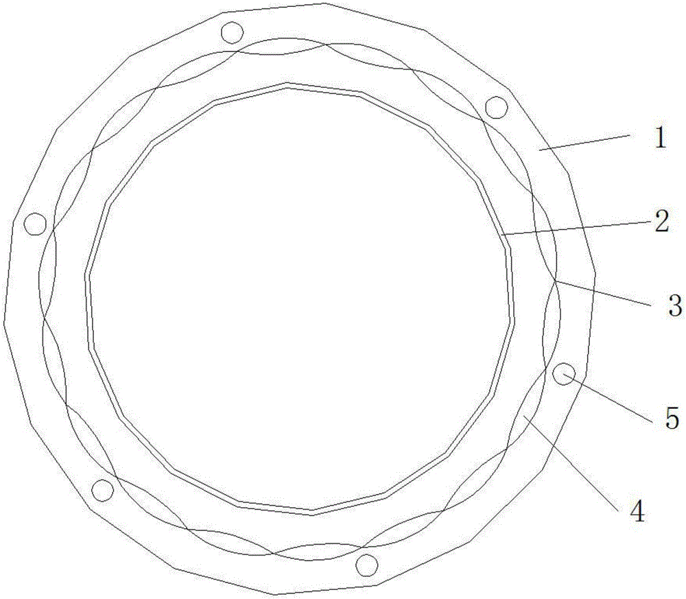
Solar vacuum heat collecting pipe and production technique thereof
A technology of vacuum heat collecting tubes and solar energy, which is applied to solar heat collectors, parts of solar heat collectors, and solar thermal energy. To achieve the effect of improving the utilization rate of light and heat, improving the heat collection effect and overcoming the poor stability
- Summary
- Abstract
- Description
- Claims
- Application Information
AI Technical Summary
Problems solved by technology
Method used
Image
Examples
Embodiment 1
[0037] A method for producing solar vacuum heat collecting tubes, comprising the following steps:
[0038] (1) The inner and outer tubes are formed, and the sections of the inner and outer tubes are regular polygons, with a thickness of more than 2mm;
[0039] (2) The glass casing is formed, its section is a regular polygon, and its edge is polished into a convex lens;
[0040] (3) Sand blasting treatment, sandblasting the outer surface of the inner pipe to make the surface roughness Ra between 12.5, using 250 mesh quartz sand, and sandblasting the outer surface of the inner pipe at a speed of 1 cubic meter per minute deal with;
[0041] (4) cleaning treatment, cleaning and drying the inner and outer walls of the inner and outer pipes;
[0042] (5) coating, copper coating is carried out on the outer surface of the inner tube;
[0043] (6) Once assembled, the inner tube and the outer tube coated with the selective absorption coating are arranged coaxially in sequence;
[00...
Embodiment 2
[0059] A method for producing solar vacuum heat collecting tubes, comprising the following steps:
[0060] (1) The inner and outer tubes are formed, and the sections of the inner and outer tubes are regular polygons, with a thickness of more than 2mm;
[0061] (2) The glass casing is formed, its section is a regular polygon, and its edge is polished into a convex lens;
[0062] (3) Sand blasting treatment, sandblasting the outer surface of the inner pipe to make the surface roughness Ra between 18.5, using 320 mesh quartz sand, and sandblasting the outer surface of the inner pipe at a speed of 1 cubic meter per minute deal with;
[0063] (4) cleaning treatment, cleaning and drying the inner and outer walls of the inner and outer pipes;
[0064] (5) coating, copper coating is carried out on the outer surface of the inner tube;
[0065] (6) Once assembled, the inner tube and the outer tube coated with the selective absorption coating are arranged coaxially in sequence;
[00...
Embodiment 3
[0081] A method for producing solar vacuum heat collecting tubes, comprising the following steps:
[0082] (1) The inner and outer tubes are formed, and the sections of the inner and outer tubes are regular polygons, with a thickness of more than 2mm;
[0083] (2) The glass casing is formed, its section is a regular polygon, and its edge is polished into a convex lens;
[0084] (3) Sand blasting treatment, sandblasting the outer surface of the inner pipe to make the surface roughness Ra between 16, using 280 mesh quartz sand, and sandblasting the outer surface of the inner pipe at a speed of 1 cubic meter per minute deal with;
[0085] (4) cleaning treatment, cleaning and drying the inner and outer walls of the inner and outer pipes;
[0086] (5) coating, copper coating is carried out on the outer surface of the inner tube;
[0087] (6) Once assembled, the inner tube and the outer tube coated with the selective absorption coating are arranged coaxially in sequence;
[0088...
PUM
| Property | Measurement | Unit |
|---|---|---|
| thickness | aaaaa | aaaaa |
| melting point | aaaaa | aaaaa |
Abstract
Description
Claims
Application Information
 - R&D Engineer
- R&D Manager
- IP Professional
- Industry Leading Data Capabilities
- Powerful AI technology
- Patent DNA Extraction
Browse by: Latest US Patents, China's latest patents, Technical Efficacy Thesaurus, Application Domain, Technology Topic, Popular Technical Reports.
© 2024 PatSnap. All rights reserved.Legal|Privacy policy|Modern Slavery Act Transparency Statement|Sitemap|About US| Contact US: help@patsnap.com


