
Optical cable peeling equipment and operating method thereof

A working method and optical cable technology, applied in the mechanical field, can solve problems such as inability to cut, low degree of intelligence, and inability to realize automatic cutting, and achieve the effect of reducing difficulty and realizing remote control

Inactive Publication Date: 2016-11-09
STATE GRID SHANDONG ELECTRIC POWER COMPANY WEIFANG POWER SUPPLY +1
View PDF7 Cites 7 Cited by
  • Summary
  • Abstract
  • Description
  • Claims
  • Application Information

AI Technical Summary

Problems solved by technology

[0003] The optical cable generally needs to be stripped during use or after it is scrapped. In the prior art, the optical cable is generally peeled manually. Specifically: first use a stripping knife to manually clamp the optical cable, and then cut the optical cable into two pieces. However, because the sheath of the optical cable is very tightly wrapped, at least two people are required to cut the sheath of the optical cable. One person holds the optical cable tightly, and the other pulls the stripping knife. A certain amount of strength is required. The labor intensity is high, and the strength of the two people is relatively balanced. so as not to cause one of the less powerful people to be dragged away by the other
In addition, there are also some optical cable stripping equipment. On the one hand, these equipment cannot cut according to the thickness of the optical cable. On the other hand, the degree of intelligence is not high, and automatic cutting cannot be realized, resulting in low stripping efficiency of the optical cable stripping equipment.

Method used


Image

  • Optical cable peeling equipment and operating method thereof
  • Optical cable peeling equipment and operating method thereof
  • Optical cable peeling equipment and operating method thereof

Examples


Embodiment Construction

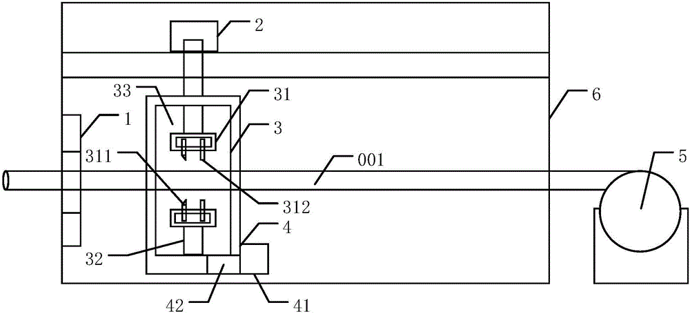
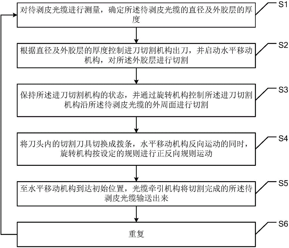
[0056] The invention discloses an optical cable stripping device and a working method thereof. The optical cable to be stripped is firstly measured by a measuring mechanism, and then the knife is fed and cut by a cutting mechanism according to the measurement result, and the cutting is controlled by a horizontal moving mechanism and a rotating mechanism. The cutting tool is switched to the method of loosening the outer rubber layer of the optical cable to be stripped by the pick bar, which can effectively cut the peeled optical cable while loosening the outer rubber layer of the optical cable to be stripped, which can greatly reduce the difficulty of optical cable stripping.

[0057] The technical solutions in the embodiments of the present invention will be described clearly and in detail below in conjunction with the accompanying drawings in the embodiments of the present invention. Obviously, the described embodiments are only part of the embodiments of the present invention,...


PUM


Abstract

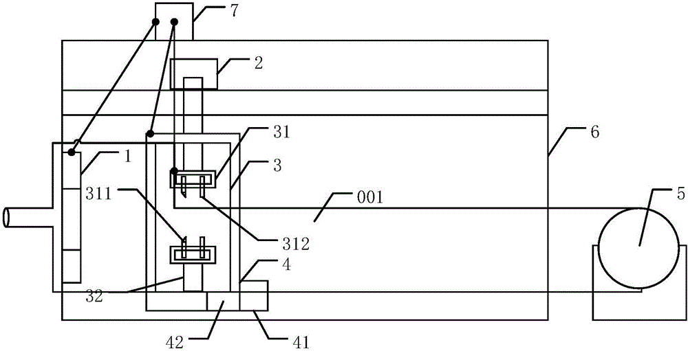
The invention discloses optical cable peeling equipment and an operating method thereof. According to the invention, an optical cable to be peeled is measured through a measuring mechanism, then a feed cutting mechanism cuts according to a measurement result, cutting is controlled by a horizontal moving mechanism and a rotating mechanism, and finally an outer rubber layer of the optical cable to be peeled is loosened through switching a cutting tool into a stirring bar, so that the outer rubber layer of the optical cable to be peeled can be loosened while the optical cable to be peeled is cut efficiently, and the peeling difficulty of the optical cable can be substantially reduced. The optical cable peeling equipment comprises a measuring mechanism, a horizontal moving mechanism, a feed cutting mechanism, a rotating mechanism and an optical cable drawing mechanism which are arranged on a rack, wherein the measuring mechanism, the feed cutting mechanism and the optical cable drawing mechanism are sequentially arranged in the horizontal direction; and the feed cutting mechanism comprises at least two cutting heads, a cutting head pushing component and a cutting head base, the at least two cutting heads are uniformly arranged in the cutting head base through the cutting head pushing component, and the cutting heads can move in the radial direction of the optical cable to be peeled through the cutting head pushing component.

Description

technical field [0001] The invention relates to the mechanical field, in particular to an optical cable stripping device and a working method thereof. Background technique [0002] Optical cables are manufactured to meet optical, mechanical or environmental performance specifications. It is a communication cable assembly that uses one or more optical fibers placed in a sheath as a transmission medium and can be used individually or in groups. [0003] The optical cable generally needs to be stripped during use or after it is scrapped. In the prior art, the optical cable is generally peeled manually. Specifically: first use a stripping knife to manually clamp the optical cable, and then cut the optical cable into two pieces. However, because the sheath of the optical cable is very tightly wrapped, at least two people are required to cut the sheath of the optical cable. One person holds the optical cable tightly, and the other pulls the stripping knife. A certain amount of str...

Claims


Application Information

Patent Timeline
Patent Type & Authority Applications(China)
IPC IPC(8): G02B6/245
CPCG02B6/245
Inventor 李中华方磊金志强许洪光刘忠军刘刚王明建黎明刘群郑冬仙肖斌周岩庞琳胡恒瑞
Owner STATE GRID SHANDONG ELECTRIC POWER COMPANY WEIFANG POWER SUPPLY
Learn More