
Advanced oxidation reactor and toxic refractory wastewater treatment device and treatment method

A wastewater treatment and reactor technology, applied in chemical instruments and methods, oxidized water/sewage treatment, special compound water treatment, etc., can solve problems such as limited mass transfer efficiency, high concentration pollutants in refractory wastewater, and high operating costs

Active Publication Date: 2019-02-15
成都柏溪环境科技有限公司
View PDF11 Cites 0 Cited by
  • Summary
  • Abstract
  • Description
  • Claims
  • Application Information

AI Technical Summary

Problems solved by technology

Adopting the above-mentioned device to treat wastewater still has the following disadvantages: (1) the required energy consumption of rotating the reactor or the packing drum is high, resulting in high operating costs; The inside of the reactor is in a fully fluidized state, and the mass transfer efficiency is limited, which is not conducive to the improvement of wastewater treatment efficiency; (3) Since the reaction tank is cylindrical, it is difficult to fully fluidize the filler by mechanical stirring and wastewater reflux, and the filler is easy to react The accumulation around the bottom of the tank is not conducive to the improvement of wastewater treatment efficiency, and the energy consumption of mechanical stirring is high, which will increase the operating cost
Although the above method can accelerate the electron transfer efficiency in the system and increase the SO 4 ·- The amount of production, but the above method is only a single persulfate oxidation method, it is difficult to effectively decompose high-concentration pollutants in wastewater by using activated persulfate oxidation alone, and it needs to consume more persulfate, and the cost of persulfate It is relatively expensive. Excessive use of persulfate will not only increase the cost of wastewater treatment but also lead to a significant increase in the salinity of the effluent, increasing the difficulty of subsequent treatment

Method used


Image

  • Advanced oxidation reactor and toxic refractory wastewater treatment device and treatment method
  • Advanced oxidation reactor and toxic refractory wastewater treatment device and treatment method
  • Advanced oxidation reactor and toxic refractory wastewater treatment device and treatment method

Examples


Embodiment 1

[0063] Embodiment 1: the advanced oxidation reactor of the first structural form

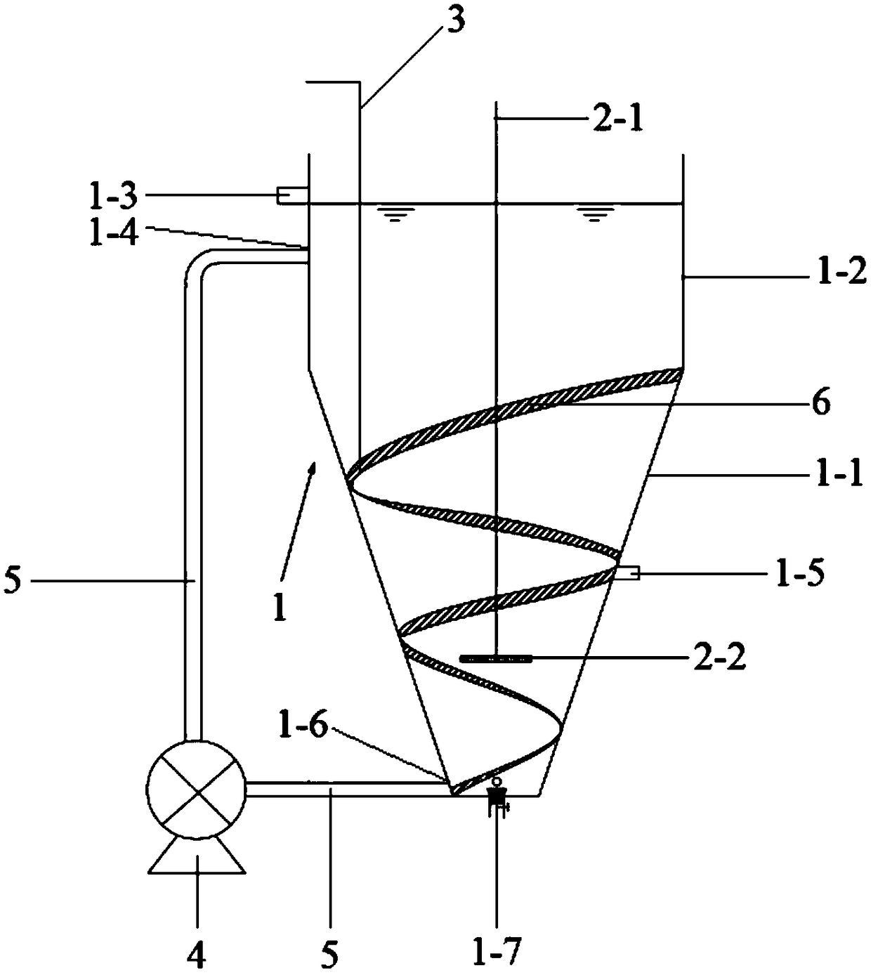
[0064] In this example, the structural schematic diagram of the advanced oxidation reactor is as follows figure 1 As shown, the reactor includes a reaction tank 1, a return pump 4, a return pipe 5, an aeration element installed in the reaction tank, a first dosing pipe 3, and a deflector 6, and the aeration element is formed by an air guide pipe 2 -1 and aeration head 2-2,

[0065] Described reaction tank 1 is made up of truncated conical body 1-1 and cylindrical body 1-2 that small end is closed, big end is open, and the internal diameter of large end of truncated conical body is equal to the internal diameter of cylindrical body, and truncated conical body 1 The large end of -1 is connected with the lower end of the cylindrical body 1-1, the ratio of the inner diameter of the large end to the small end of the frusto-conical cylindrical body 1-1 of the reaction tank is 3:1, and the height of t...

Embodiment 2

[0068] Embodiment 2: the advanced oxidation reactor of the first structural form

[0069] In this example, the structural schematic diagram of the advanced oxidation reactor is as follows figure 1 As shown, the reactor includes a reaction tank 1, a return pump 4, a return pipe 5, an aeration element installed in the reaction tank, a first dosing pipe 3, and a deflector 6, and the aeration element is formed by an air guide pipe 2 -1 and aeration head 2-2,

[0070] Described reaction tank 1 is made up of truncated conical body 1-1 and cylindrical body 1-2 that small end is closed, big end is open, and the internal diameter of large end of truncated conical body is equal to the internal diameter of cylindrical body, and truncated conical body 1 The large end of -1 is connected with the lower end of the cylindrical body 1-1, the ratio of the inner diameter of the large end to the small end of the frusto-conical cylindrical body 1-1 of the reaction tank is 4:1, and the height of t...

Embodiment 3

[0073] Embodiment 3: the advanced oxidation reactor of the second structural form

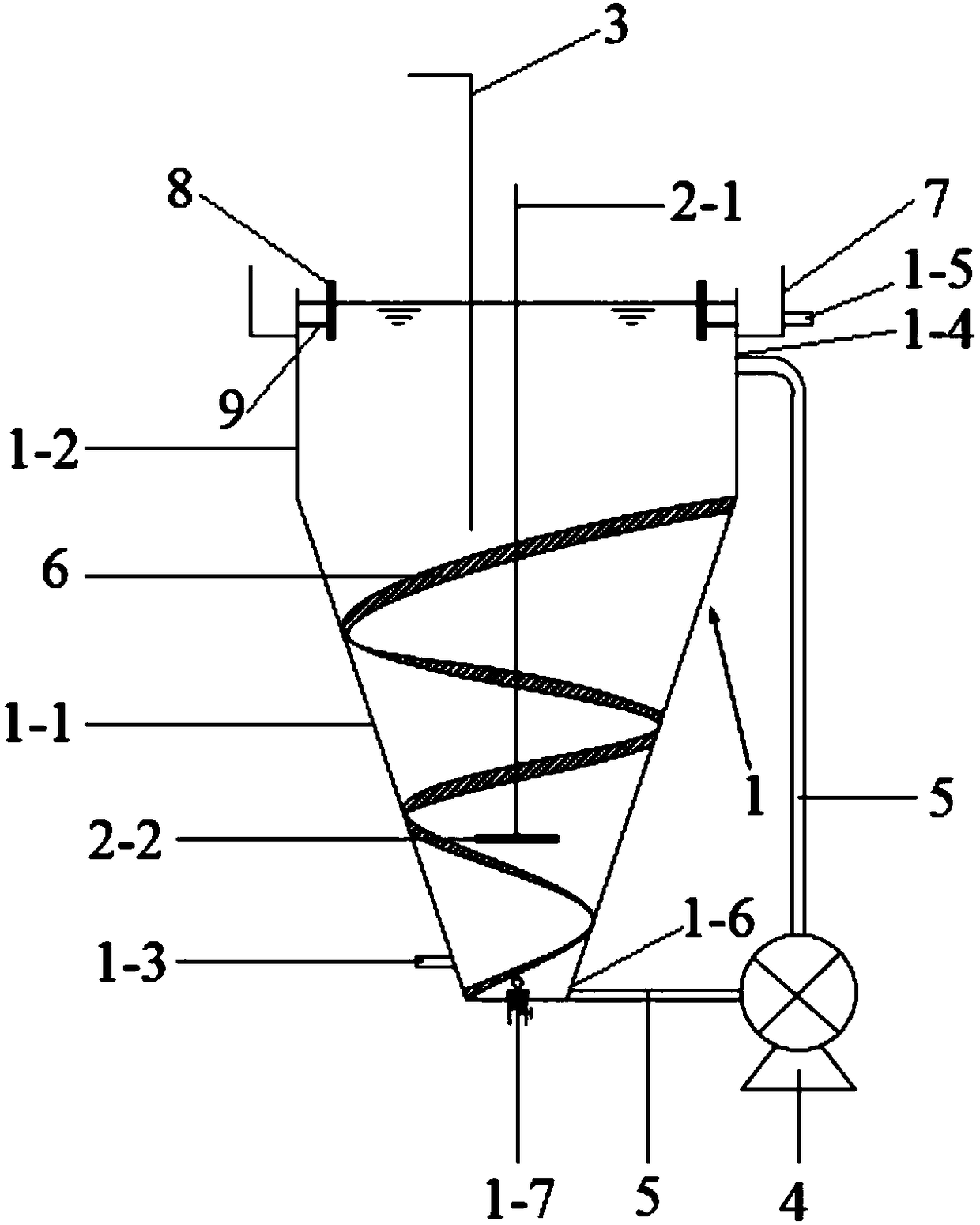
[0074] In this example, the structural schematic diagram of the advanced oxidation reactor is as follows figure 2 As shown, the reactor includes a reaction tank 1, a return pump 4, a return pipe 5, an aeration element installed in the reaction tank and a first dosing pipe 3, a deflector 6, an outlet weir 7 and an annular baffle 8, The aeration element is composed of an air duct 2-1 and an aeration head 2-2,

[0075] Described reaction tank 1 is made up of truncated conical body 1-1 and cylindrical body 1-2 that small end is closed, big end is open, and the internal diameter of large end of truncated conical body is equal to the internal diameter of cylindrical body, and truncated conical body 1 The large end of -1 is connected with the lower end of the cylindrical body 1-1, the ratio of the inner diameter of the large end to the small end of the frusto-conical cylindrical body 1-1 of the reac...


PUM


Abstract

The invention belongs to the field of toxic and refractory wastewater treatment and provides advanced oxidation reactors with two structural forms and toxic and refractory wastewater treatment devices with two structural forms. Each toxic and refractory wastewater treatment device integrates three stages of reactors through coupling. The invention further provides toxic and refractory wastewater treatment methods. According to the methods, persulfate and a micro-grade microelectrolysis material are added to first-stage reactors of the wastewater treatment devices, hydrogen peroxide and persulfate are added to second-stage reactors, the micro-grade microelectrolysis material is added to second-stage reactors, and then a Fenton-like reaction, a Fenton reaction and an activated persulfate oxidization reaction are effectively coupled in the three stages of reactors; with the adoption of the methods, the wastewater treatment effect can be enhanced and improved, and the wastewater treatment cost can be reduced.

Description

technical field [0001] The invention belongs to the field of toxic and refractory wastewater treatment, and in particular relates to an advanced oxidation reactor, a device for treating toxic and refractory wastewater and a method for treating toxic and refractory wastewater. Background technique [0002] At present, advanced oxidation technologies such as Fenton-like reaction, Fenton reaction and new activated persulfate oxidation are mainly used for pretreatment or advanced treatment of toxic and refractory wastewater. The Fenton-like reaction refers to the reaction of zero-valent iron or iron-based multimetallic materials under aerobic conditions to convert O 2 reduced to H 2 o 2 , then at Fe 2+ Under the catalysis of catalysis, strong oxidizing hydroxyl radicals (OH) are generated in situ, and the reaction equations are shown in formulas (1)-(2); Fenton reaction refers to H 2 o 2 in Fe 2+ Under the catalytic action of OH, strong oxidizing OH is produced, and the re...

Claims


Application Information

Patent Timeline
Patent Type & Authority Patents(China)
IPC IPC(8): C02F1/72C02F1/461C02F9/06B01J8/24
CPCB01J8/24C02F1/4672C02F1/66C02F1/72C02F1/722C02F9/00C02F2209/005C02F2209/06C02F2209/08C02F2301/046C02F2301/08C02F2305/026
Inventor 赖波袁月
Owner 成都柏溪环境科技有限公司
Learn More