
The workpiece output structure of the rectangular multi-leg stirrup welding device for shear walls

A technology for outputting structures and welding devices, applied in welding equipment, welding/welding/cutting items, manufacturing tools, etc., which can solve the problems of cumbersome consumption and limited processing efficiency of rectangular multi-leg stirrups

Active Publication Date: 2018-05-04
CHINA METALLURGICAL CONSTR ENG GRP
View PDF8 Cites 0 Cited by
  • Summary
  • Abstract
  • Description
  • Claims
  • Application Information

AI Technical Summary

Problems solved by technology

[0005] Rectangular steel bars and stirrup legs need to be manually installed to the stirrup fixed formwork one by one, which is still relatively cumbersome and wasteful, which limits the improvement of the processing efficiency of rectangular multi-leg stirrups

Method used


Image

  • The workpiece output structure of the rectangular multi-leg stirrup welding device for shear walls
  • The workpiece output structure of the rectangular multi-leg stirrup welding device for shear walls
  • The workpiece output structure of the rectangular multi-leg stirrup welding device for shear walls

Examples


Embodiment Construction

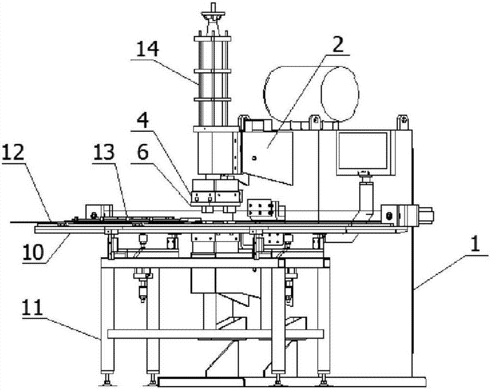
[0066] The present invention will be described in further detail below in conjunction with the accompanying drawings of a rectangular multi-leg stirrup welding device for a shear wall of the present invention. Wherein, the descriptive terms such as up, down, left, right, etc. are used for the description, with the purpose of helping readers to understand, but not intended to limit. In the following description, the side where the material input side is located is the front, and the side where the output side is located is the rear.

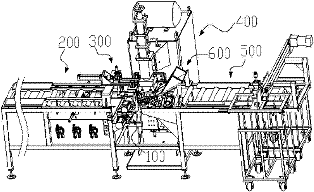
[0067] Rectangular multi-leg stirrup welding device for shear walls (such as image 3 As shown), including a welding machine 400, the welding machine 400 includes two sets of welding electrodes vertically opposite to each other, the lower set of the two sets of welding electrodes is a fixed set of lower welding electrodes, and the upper set of welding electrodes It is the upper welding electrode; the upper welding electrode is integrally installe...


PUM


Abstract

The invention discloses a workpiece output structure for a rectangular multi-rib stirrup welding device for a shear wall. The workpiece output structure is characterized by comprising an output roller way which is integrally installed on one side, away from a reinforcing steel bar clamping and conveying structure, beside a lower welding electrode of a welding machine. The output roller way comprises a support and conveying rollers. The whole support is of a long-strip-like rectangular framework structure. The multiple conveying rollers are distributed and installed horizontally in the length direction of the support. The upper end face of each conveying roller is a conveying surface flush with the upper surface of an electrode tip of the lower welding electrode of the welding machine. The workpiece output structure further comprises a pressing roller. The pressing roller is fixedly installed over the conveying rollers of the front end of the output roller way in a rotating manner. The pressing roller in the workpiece output structure can increase friction force between rectangular multi-rib stirrups and the conveying rollers, the rectangular multi-rib stirrups are output smoothly through the output roller way, and while continuous production and machining of the rectangular multi-rib stirrups can be achieved better, the welding machine is available and can carry out next welding operation.

Description

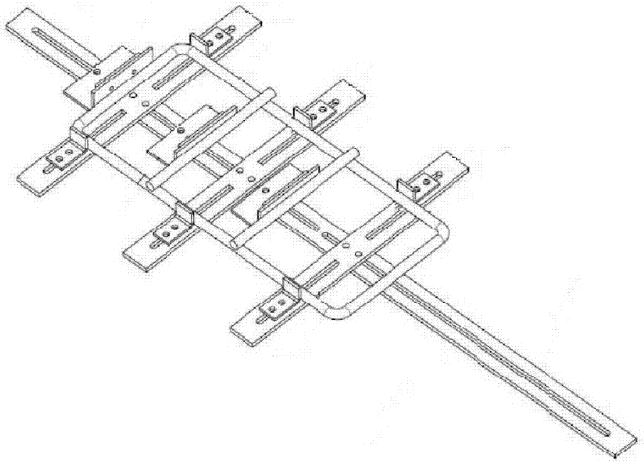
technical field [0001] The invention belongs to the field of shear wall stirrup welding devices, in particular to a workpiece output structure of a rectangular multi-leg stirrup welding device for shear walls. Background technique [0002] Shear walls, also known as wind-resistant walls or earthquake-resistant walls, are walls in houses or structures that mainly bear horizontal loads caused by wind loads or earthquakes, and can prevent structures from being damaged by horizontal loads. The shear wall is constructed by pouring concrete on the steel skeleton. The steel skeleton is fixedly connected by longitudinal bars and stirrups. The rectangular multi-leg stirrup is a kind of stirrup commonly used in the shear wall. [0003] At present, rectangular multi-leg stirrups are usually processed by the following methods: First, make a stirrup fixed formwork (such as figure 2 As shown), install the rectangular steel bar and multiple stirrup limbs to be welded on the stirrup fixing...

Claims


Application Information

Patent Timeline
Patent Type & Authority Patents(China)
IPC IPC(8): B23K11/36B23K101/30
CPCB23K11/36
Inventor 刘赫凯李智能杨炬陈刚蒋玉富石春雷
Owner CHINA METALLURGICAL CONSTR ENG GRP
Learn More