
Microparticle Manufacturing Method

一种制造方法、微粒的技术,应用在化学仪器和方法、含有效成分的医用配制品、医药配方等方向,能够解决难以稳定制作微粒、残留改善的余地、难以制作均匀且均质的微粒等问题

Inactive Publication Date: 2018-05-08
M TECH CO LTD
View PDF10 Cites 0 Cited by
  • Summary
  • Abstract
  • Description
  • Claims
  • Application Information

AI Technical Summary

Problems solved by technology

[0005] However, even in the case of using the method described in Patent Document 3, it may be difficult to stably produce fine particles. When producing fine particles containing two or more molecules and elements, the local element ratio may vary. Even, it may be difficult to produce uniform and homogeneous particles
[0006] Furthermore, even if the method described in Patent Document 4 is used in combination, if the operating conditions of the device such as the formulation of the fluid to be processed, the liquid delivery amount, the temperature, and the rotational speed of the processing surface are simply changed, the resulting However, it is difficult to realize the desired crystallinity, crystal form or composition ratio of a specific crystal form, and no specific method for freely controlling the properties / characteristics of the particles such as crystallinity, crystal form or composition ratio of a specific crystal form has been disclosed, room for improvement

Method used


Image

  • Microparticle Manufacturing Method
  • Microparticle Manufacturing Method
  • Microparticle Manufacturing Method

Examples


Embodiment 1~3

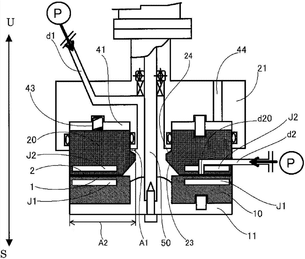
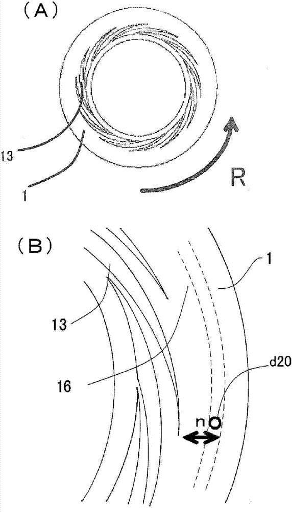
[0255] use figure 1 In the fluid processing device shown in , the pigment solution and the precipitation solvent as the particle raw material solution are arranged oppositely, have accessible and / or separate processing surfaces, and at least one of them rotates relative to the other. Mix in the thin film fluid formed between 1 and 2, and precipitate the pigment particles in the thin film fluid. In the preparation of the pigment solution, a stirrer with a rotating stirring blade is used, and at least one of the three conditions (stirring time, stirring blade circumferential speed, and temperature of the particle raw material solution) of the predetermined stirring energy is changed, Increase or decrease stirring energy. In Examples 1 to 3, the stirring energy was increased or decreased by changing the temperature (preparation temperature) of the pigment solution.

[0256] First, use Figure 4 and Figure 5 A stirrer (Clearmix (manufactured by Em Technic Co., Ltd.)) having r...

Embodiment 4~16

[0266] Except having changed the preparation conditions of the pigment solution into any of Tables 3-5, it carried out similarly to the case of Examples 1-3, and obtained the dry powder of PR122 microparticles|fine-particles. The results are shown in Tables 3-5. In Examples 4 to 16, the stirring energy was increased or decreased by changing the stirring time (preparation time) of the pigment solution as the second fluid.

[0267] [table 3]

[0268]

[0269] [Table 4]

[0270]

[0271] [table 5]

[0272]

[0273] The changes in the crystallinity / average particle diameter and β-type crystal ratio / average particle diameter of PR122 fine particles with respect to the preparation time of the second fluid in Examples 4 to 7 are shown in Figure 7 , the changes in the crystallinity / average particle diameter and β-type crystal ratio / average particle diameter of PR122 particles with respect to the preparation time of the second fluid in Examples 8 to 11 are shown in Figur...

Embodiment 17~22

[0277] The preparation conditions of the pigment solution were changed to those in Table 6 or 7, and it was carried out in the same manner as in Examples 1 to 3 to obtain a dry powder of PR122 fine particles. The results are shown in Tables 6-7. In Examples 17 to 22, the stirring energy was increased or decreased by changing the circumferential speed of the stirring blades at the time of preparing the pigment solution as the second fluid.

[0278] [Table 6]

[0279]

[0280] [Table 7]

[0281]

[0282] In Examples 17 to 22, changes in the crystallinity / average particle diameter of the PR122 microparticles with respect to the peripheral speed of the stirring blade during the preparation of the second fluid are shown in Figure 12 , the changes in the β-type crystal ratio / average particle diameter of the PR122 microparticles with respect to the peripheral speed of the stirring blade during the preparation of the second fluid in Examples 17 to 22 are shown in Figure 13 ...


PUM


Abstract

Provided is a method for producing fine particles, comprising: a dissolving step of dissolving at least one kind of fine particle raw materials in a solvent using a stirrer having a rotating stirring blade to obtain a fine particle raw material solution; At least one of the precipitated solvents and the fine particle raw material solution are introduced between at least two processing surfaces that are oppositely arranged, accessible and / or separate, and at least one of them rotates relative to the other. This is a precipitation step in which fine particles are precipitated by mixing in the thin film fluid formed between the treatment surfaces. In the above-mentioned dissolving step, the stirring energy specified by the stirring time conditions using the stirrer, the peripheral speed conditions of the stirring blades, and the temperature conditions of the fine particle raw material solution is increased or decreased by changing at least one of the above conditions. , by increasing or decreasing the stirring energy, the crystallinity and crystal form of the particles obtained in the precipitation step are controlled.

Description

technical field [0001] The present invention relates to a method for producing microparticles. Background technique [0002] Microparticles such as metals, oxides, pharmaceuticals, foods, cosmetics, and other living body ingestible substances, and pigments are required in a wide range of fields in the industry. [0003] The production method of microparticles generally uses a flask, a beaker, a tank, etc. as described in Patent Document 1 to perform reactions such as poor solvent method, crystallization, oxidation, and reduction. It is difficult to uniformly maintain the concentration and temperature in the container, so the particle size distribution of the obtained particles tends to widen. In addition, in the case of producing fine particles such as alloys and composite oxides containing two or more elements, it is difficult to obtain them in a homogeneous manner. Element ratios make particles. In addition, a method for producing microparticles using a microreactor as d...

Claims


Application Information

Patent Timeline
Patent Type & Authority Patents(China)
IPC IPC(8): B01J19/00C09B48/00C09B67/14C09B67/20A61K31/405
CPCB01J19/1887A61K31/405B01J19/0066B01J19/18B01J4/002B01J2219/00772B01J2219/00779C09B67/009C09B67/0097B01F23/41B01F27/2712B01F27/812B01F27/84B01F27/86B01F27/9214A61K8/492C09B48/00B01F27/90B01F21/10B01F35/2115B01F35/22142B01F21/50B01F2101/30C09B67/0036C09B67/0095
Inventor 榎村真一
Owner M TECH CO LTD
Learn More