
Automobile exhaust pipe flange manufacturing device and method

A technology for automobile exhaust and manufacturing equipment, which is applied in special data processing applications, instruments, electrical digital data processing, etc., and can solve problems such as low production efficiency and material utilization, low flange surface processing quality, and reduced product service life, etc. problems, to achieve high production efficiency, high mechanical performance, and low production costs

Inactive Publication Date: 2016-10-12
SHANGHAI DIANJI UNIV
View PDF5 Cites 1 Cited by
  • Summary
  • Abstract
  • Description
  • Claims
  • Application Information

AI Technical Summary

Problems solved by technology

[0003] At present, in the field of vehicles, flanges are often used to connect the exhaust pipes. Due to the high temperature and harsh working environment of the exhaust system, it is particularly important to ensure a good seal on the flange surface. If The processing quality of the flange surface is not high, and gas leakage is easy to occur
[0004] At present, the automobile exhaust pipe flanges on the market adopt machining or hot forging methods, the production efficiency and material utilization rate are low, resulting in high cost, and at the same time, the strength performance is also poor, and it is easy to be damaged under high temperature, which reduces the use of products. number of years

Method used


Image

  • Automobile exhaust pipe flange manufacturing device and method
  • Automobile exhaust pipe flange manufacturing device and method
  • Automobile exhaust pipe flange manufacturing device and method

Examples


Embodiment Construction

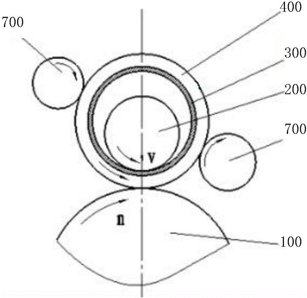
[0035] The specific embodiments of the present invention are given below in conjunction with the accompanying drawings, but the present invention is not limited to the following embodiments. Advantages and features of the present invention will be apparent from the following description and claims. It should be noted that all the drawings are in very simplified form and use imprecise ratios, which are only used for the purpose of conveniently and clearly assisting in describing the embodiments of the present invention.

[0036] Please refer to Figure 1 ~ Figure 3 , figure 1 Shown is a top view of the structure of the automobile exhaust pipe flange manufacturing device according to the preferred embodiment of the present invention. figure 2 Shown is the front view of the structure of the automobile exhaust pipe flange manufacturing device according to the preferred embodiment of the present invention. image 3 Shown is a structural perspective view of an automobile exhaust...


PUM


Abstract

The invention provides an automobile exhaust pipe flange manufacturing device and method. The automobile exhaust pipe flange manufacturing device comprise a main roller serving as a driving roller to continuously rotate in the circumferential direction at a set angular speed, and a core roller peripherally provided with a flange ring blank and a die, serving as an impression roller, performing continuous feeding towards the main roller at a set speed and rotating under the driving of a friction force produced with the contact face of the flange ring blank, wherein the die changes an outer outline shape of the flange ring blank in the process, and the flange ring blank between the main roller and the core roller is stressed in the thickness direction and extends in the circumferential direction to make wall thickness decreased and make inner and outer diameters increased simultaneously. The automobile exhaust pipe flange manufacturing device adopts the annular roll-forming method, namely extrudes out a flange through thick-plate spinning, the method adopts a plate to replace a rod, and the material cost can be reduced by one third. In addition, follow-up machining allowance is small, and meanwhile the annular roll-forming method has the advantages of being good in machining quality, high in production efficiency, low in production cost, high in material utilization rate and the like.

Description

technical field [0001] The invention relates to the field of automobile parts manufacturing, and in particular to an automobile exhaust pipe flange manufacturing device and manufacturing method. Background technique [0002] The main function of the exhaust pipe of the car is to increase the air intake of the engine, thereby increasing the power and torque of the engine, and making the engine performance more stable. With the development of the automobile industry, the exhaust pipe, as an indispensable component of the automobile engine, is directly connected to the cylinder head. important role. [0003] At present, in the field of vehicles, flanges are often used to connect the exhaust pipes. Due to the high temperature and harsh working environment of the exhaust system, it is particularly important to ensure a good seal on the flange surface. If The processing quality of the flange surface is not high, and gas leakage is easy to occur. [0004] At present, the automob...

Claims


Application Information

Patent Timeline
IPC IPC(8): G06F17/50
CPCG06F30/15G06F30/23G06F2119/18Y02T90/00
Inventor 周建峰马昌龙罗孔逍
Owner SHANGHAI DIANJI UNIV
Learn More