Exhaust gas temperature control system

A technology of exhaust temperature and control system, which is applied in the direction of exhaust device, muffler device, engine components, etc. It can solve the problem that it is difficult to meet the exhaust emission control requirements of diesel engines, the exhaust temperature cannot reach 250°C, and the conversion efficiency of the post-treatment system is low. and other issues to achieve the effect of reducing cost and power consumption, reducing dependence, and reducing pollutant emissions

Inactive Publication Date: 2016-10-12
TONGJI UNIV
View PDF8 Cites 10 Cited by
  • Summary
  • Abstract
  • Description
  • Claims
  • Application Information

AI Technical Summary

Problems solved by technology

[0003] Although there are many studies on post-treatment systems, the temperature window of the existing catalytic system is relatively high and narrow, which is difficult to meet the control requirements of diesel engine exhaust emissions. The activity and selectivity of the catalyst need to be further improved to meet the increasingly stringent requirements. emission regulations
At present, the reaction temperature of the main reducing agent in SCR is above 250°C; DPF regeneration needs to reach above 550°C, and in cold start and idling conditions, the exhaust temperature cannot reach 250°C, the conversion of the aftertreatment system The efficiency is very low. Therefore, the core issue of the research on the aftertreatment performance of the diesel engine is the control of the exhaust temperature, that is, the thermal management of the exhaust system.

Method used


Image

  • Exhaust gas temperature control system
  • Exhaust gas temperature control system
  • Exhaust gas temperature control system

Examples


Embodiment Construction

[0028] The present invention will be described in detail below in conjunction with the accompanying drawings and specific embodiments.

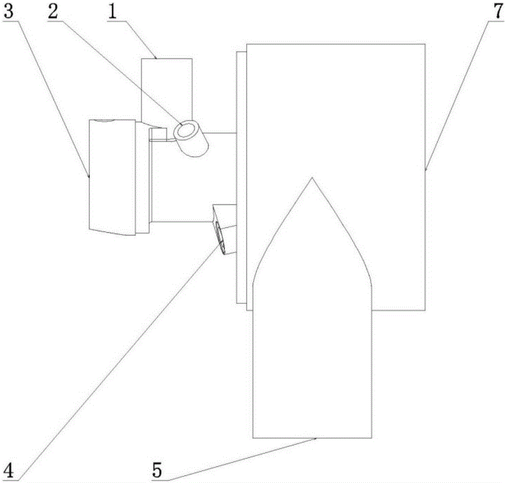
[0029] Such as figure 1 -2, a kind of exhaust temperature control system is used in the automobile after-treatment system to increase the exhaust temperature of the automobile, including an oil-gas mixing unit, a burner 6 and an exhaust chamber 12 arranged in sequence,

[0030] The oil-air mixing unit includes an oil-air mixing chamber, a fuel injector 3, a first-layer atomizer 9 and a second-layer atomizer 10. In the chamber, the auxiliary air inlet 1 and the glow plug hole 2 are all arranged on the oil-air mixing chamber, and the fuel injector 3 is connected with the fuel tank of the automobile through an electronically controlled oil pump.

[0031] When the oil-air mixing unit is working, a heating plug 8 is inserted into the glow plug hole 2 to heat the oil ejected from the injector 3, making the oil easier to be atomized, and then the o...


PUM


Abstract

The invention relates to an exhaust gas temperature control system which is used for an aftertreatment system of an automobile. The exhaust gas temperature control system is used for increasing the exhaust gas temperature of the automobile. The exhaust gas temperature control system comprises an oil-gas mixing unit, a combustor (6) and a waste gas cavity (12) which are arranged in sequence. The oil-gas mixing unit is connected with a fuel oil tank of the automobile. The oil-gas mixing unit comprises an auxiliary air inlet (1) and a glow plug hole (2). The auxiliary air inlet (1) is connected with a compressed air tank arranged on the automobile. A sparking plug hole (4) is formed in the combustor (6). The waste gas cavity (12) is connected with an exhaust port (5) of an automobile engine. Compared with the prior art, by the adoption of the exhaust gas temperature control system, the independence on auxiliary air is reduced, no independent air pump is needed, the cost is low, and the exhaust gas temperature control system has great application value in aftertreatment equipment.

Description

technical field [0001] The invention relates to a device used in a diesel engine or a gasoline engine vehicle to heat the exhaust gas of the engine so as to realize the heat management of the exhaust system and realize the instantaneous controllability of the exhaust temperature, especially relates to an exhaust gas temperature control system. Background technique [0002] The emission pollutants of diesel engines are mainly NOX (nitrogen oxides) PM (particulates), and SCR (Selective Catalytic Reduction) and DPF (Particulate Filter) are effective ways to reduce these emissions. At present, the SCR system using ammonia water as a reducing agent can reduce diesel engine NOX emissions by more than 95%; the use of DPF can reduce PM emissions by more than 90%. [0003] Although there are many studies on post-treatment systems, the temperature window of the existing catalytic system is relatively high and narrow, which is difficult to meet the control requirements of diesel engin...

Claims


Application Information

Patent Timeline
Patent Type & Authority Applications(China)
IPC IPC(8): F01N3/025F01N3/027F01N3/035
CPCF01N3/025F01N3/027F01N3/035
Inventor 王琦玮倪计民石秀勇陈沁青李佳琪刘越
Owner TONGJI UNIV
Why Eureka
Try Eureka