
Fluid magnetizer

A fluid magnetizer and fluid pipeline technology, applied in chemical instruments and methods, magnetic objects, machines/engines, etc., can solve the problems of improving pipelines, leakage risk, unsatisfactory treatment effect, etc., to improve water quality and improve efficiency. The effect of penetration

Inactive Publication Date: 2016-10-12
BEIJING SMHW MAGNETIZATION TECH CO LTD
View PDF6 Cites 10 Cited by
  • Summary
  • Abstract
  • Description
  • Claims
  • Application Information

AI Technical Summary

Problems solved by technology

[0003] However, the structure of the current magnetizer is complicated, the distribution of the formed spatial magnetic field is unreasonable, and the processing effect is not ideal.
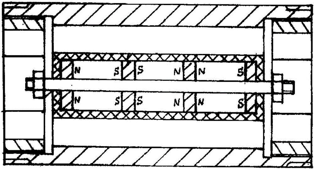
[0004] The patent application number is: the disclosed magnetizer of CN03206286.9 (see specifically figure 1 ), the magnets are arranged along the central axis of the pipeline, and the direction of the formed magnetic field is parallel to the direction of fluid flow. Experiments have proved that the magnetic treatment effect of the magnetic field parallel to the direction of fluid flow is poor
In addition, when installing this kind of magnetizer, it is necessary to cut off the original pipeline and process the connection joint to install the connection. On the one hand, the production must be stopped during installation, and on the other hand, there is an additional possible leakage point, which increases the risk of pipeline leakage.
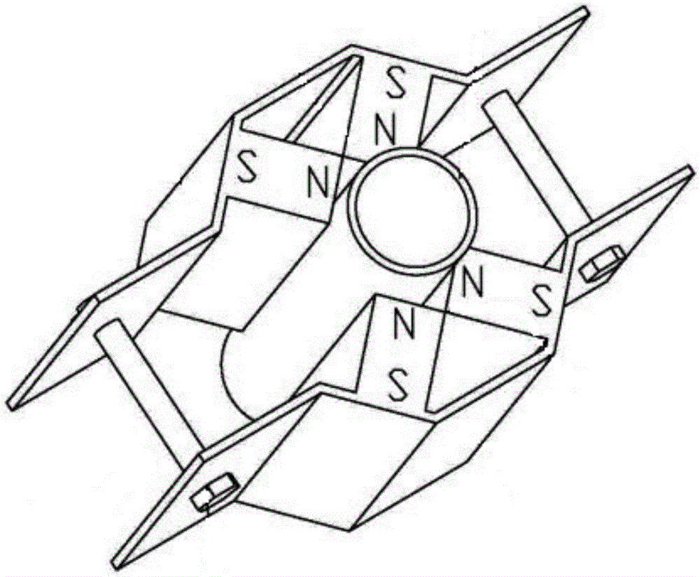
[0005] The patent application number is the magnetizer published by CN104752017A (such as figure 2 The magnetizer shown), the ends near the wall of the treatment fluid pipe are of the same polarity (for example: as figure 2 Near the fluid pipe wall are all N poles), so that the spatial monopole magnetic field can be formed on the pipe section; however, it is obvious that the monopole magnetic field makes the magnetic field strength in the center of the fluid pipe very weak, and the magnetization effect is not strong

Method used


Image

  • Fluid magnetizer
  • Fluid magnetizer
  • Fluid magnetizer

Examples


Embodiment Construction

[0037] The technical solutions of the present invention will be clearly and completely described below in conjunction with the accompanying drawings. Apparently, the described embodiments are some of the embodiments of the present invention, but not all of them. Based on the embodiments of the present invention, all other embodiments obtained by persons of ordinary skill in the art without making creative efforts belong to the protection scope of the present invention.

[0038] In the description of the present invention, it should be noted that the terms "center", "upper", "lower", "left", "right", "vertical", "horizontal", "inner", "outer" etc. The indicated orientation or positional relationship is based on the orientation or positional relationship shown in the drawings, and is only for the convenience of describing the present invention and simplifying the description, rather than indicating or implying that the referred device or element must have a specific orientation, ...


PUM


Abstract

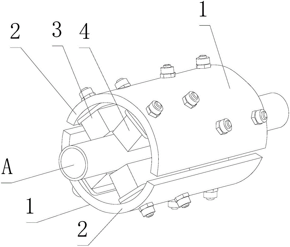
The invention discloses a fluid magnetizer. The fluid magnetizer comprises a plurality of split magnetization assemblies; the plurality of split magnetization assemblies are arranged around a fluid pipeline along the circumference direction; every split magnetization assembly comprises a magnetic conduction shell and two rows of magnetic block groups arranged on the inner wall of the magnetic conduction shell; the magnetic block groups are mutually staggered and are arranged on the outer wall of the magnetic conduction shell at intervals; every row of the magnetic block groups is formed by a plurality of magnetic block groups; if the fluid magnetizer is arranged on an oil inlet pipeline, 8-18% automobile oil saving and 38-94% tail gas pollutant NO discharge are realized; and if the fluid magnetizer is arranged on a tap water inlet pipeline, the water quality is improved, the water molecule cluster structure is refined, and scale inhibition and sterilization functions are realized. The fluid magnetizer has the advantages of convenience in installation, strong magnetization effect, and novel and reasonable structure design.

Description

technical field [0001] The invention relates to the technical field of magnetizer equipment, in particular to a fluid magnetizer. Background technique [0002] As we all know, magnetizers are used in chemical, mining, metallurgy, building materials, and other industrial fields, as well as in agriculture and medicine. The functions of sterilization, scale inhibition, environmental protection and energy saving, and improvement of process reaction speed have been confirmed by a large number of experiments and applications. It is a long-term technical requirement of economic and social development to provide a magnetizer with high efficiency, energy saving, simple structure and convenient installation. [0003] However, the structure of the current magnetizer is complex, the distribution of the formed spatial magnetic field is unreasonable, and the processing effect is not ideal. [0004] The patent application number is: the disclosed magnetizer of CN03206286.9 (see specifical...

Claims


Application Information

Patent Timeline
IPC IPC(8): C02F1/48H01F13/00F02M27/04C02F103/02
CPCH01F13/003F02M27/045C02F1/48C02F2303/22C02F2307/14C02F2103/02C02F2303/04Y02T10/12
Inventor 赵俊兰李振锁
Owner BEIJING SMHW MAGNETIZATION TECH CO LTD
Learn More