Cooling tower with feeding mechanism

A feeding mechanism and cooling tower technology, applied in the direction of conveyor objects, transportation and packaging, cleaning devices, etc., can solve the problems affecting the cooling tower work, cooling tower lack of feeding mechanism, inconvenient material transfer, etc.

Inactive Publication Date: 2016-10-12
徐秀
View PDF9 Cites 0 Cited by
  • Summary
  • Abstract
  • Description
  • Claims
  • Application Information

AI Technical Summary

Problems solved by technology

[0002] Cooling towers are often used to cool products during the manufacturing process of products. Cooling towers use water as a circulating coolant to absorb heat from a system and discharge it to the atmosphere to reduce the water temperature; its cooling is to use water and After the air flows and contacts, it performs cold and heat exchange to generate steam. The steam volatilizes and takes away heat to achieve evaporation heat dissipation, convective heat transfer and radiation heat transfer to dissipate the waste heat generated in industry or in refrigeration and air conditioning to reduce the water temperature. To ensure the normal operation of the system, the device is generally barrel-shaped, so it is called a cooling tower. The cooling tower is a device that can quickly cool a large amount of materials. The cooling tower is simple in structure and easy to operate, but traditional cooling towers often lack relevant The feeding mechanism relies too much on manual feeding, which greatly affects the cooling work of the cooling tower, and the traditional cooling tower is not convenient to transfer the cooled material, which again affects the work of the cooling tower

Method used


Image

  • Cooling tower with feeding mechanism
  • Cooling tower with feeding mechanism

Examples


Embodiment Construction

[0014] The following will clearly and completely describe the technical solutions in the embodiments of the present invention with reference to the accompanying drawings in the embodiments of the present invention. Obviously, the described embodiments are only some, not all, embodiments of the present invention. Based on the embodiments of the present invention, all other embodiments obtained by persons of ordinary skill in the art without making creative efforts belong to the protection scope of the present invention.

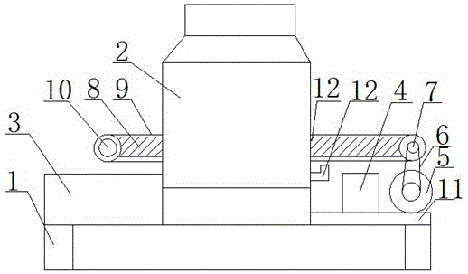
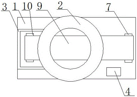
[0015] see Figure 1-2 It can be seen that the present invention provides: a cooling tower with a feeding mechanism, including a support frame 1, a cooling tower body 2, a material storage box 3, an electric control box 4, a motor 5, a connecting belt 6, a driving roller 7, and a connecting rod 8 , transmission crawler belt 9, load-bearing drum 10, support plate 11, nozzle 12 and feeding mechanism 13, the top of support frame 1 is provided with cooling tower b...


PUM


Abstract

The invention relates to a cooling tower with a feeding mechanism. The cooling tower comprises a support frame, a cooling tower body, a storage box, an electric control box, a motor, a connecting belt, a transmission roller, a connecting rod, a transmission track, a bearing roller, a support plate, a nozzle and a feeding mechanism; the cooling tower body is arranged at the top of the support frame; the storage box is arranged on one side of the cooling tower body; the support plate is arranged on the other side of the cooling tower body; the electric control box is arranged at the top of the support plate; the feeding mechanism is arranged on one side of the cooling tower body, and includes the transmission roller, the connecting rod, the transmission track and the bearing roller; one end of the connecting rod is rotationally connected with the transmission roller, and the other end of the connecting rod is rotationally connected with the bearing roller; and the transmission track is arranged between the bearing roller and the transmission roller. The cooling tower with the feeding mechanism is convenient to send materials in and out the cooling tower, so that the cooling tower is convenient to use.

Description

technical field [0001] The invention relates to the technical field of processing equipment, in particular to a cooling tower with a feeding mechanism. Background technique [0002] Cooling towers are often used to cool products during the manufacturing process of products. Cooling towers use water as a circulating coolant to absorb heat from a system and discharge it to the atmosphere to reduce the water temperature; its cooling is to use water and After the air flows and contacts, it performs cold and heat exchange to generate steam. The steam volatilizes and takes away heat to achieve evaporation heat dissipation, convective heat transfer and radiation heat transfer to dissipate the waste heat generated in industry or in refrigeration and air conditioning to reduce the water temperature. To ensure the normal operation of the system, the device is generally barrel-shaped, so it is called a cooling tower. The cooling tower is a device that can quickly cool a large amount of...

Claims


Application Information

Patent Timeline
IPC IPC(8): B65G47/74B65G45/22
CPCB65G47/74B65G45/22
Inventor 徐秀
Owner 徐秀
Why Eureka
Try Eureka