Sewage flow-pushing sundry separator

A technology for separators and sundries, applied in water/sewage treatment, water/sludge/sewage treatment, chemical instruments and methods, etc., can solve problems such as difficult maintenance, corrosion and easy damage of thrusters, and improve the use of The effect of maintenance work, reducing push flow resistance, and increasing push flow effect

Inactive Publication Date: 2016-10-05
苏州市和源环保科技有限公司
View PDF6 Cites 1 Cited by
  • Summary
  • Abstract
  • Description
  • Claims
  • Application Information

AI Technical Summary

Problems solved by technology

[0004] The disadvantages in the prior art are: due to the increased diameter of the impeller of the submersible flowmaker, when low-speed rotation is required, the sundries and sludge in the sewage cause the submersible flowmaker to bear a large impact load, which affects the life of the submersible flowmaker. The impact is relatively large; it even directly affects the service life of the flowmaker; the existing submersible flowmaker is horizontally installed on the bracket at the bottom of the pool, and it is difficult to install, lift and maintain, resulting in the actual use and maintenance of the submersible flowmaker on site. , It is often very difficult to adjust; in order to make the sewage uniform everywhere and maintain the flow of sewage in the pool, the submersible flowmeter used in the condition of many impurities and harsh environment, long-term continuous operation may easily cause corrosion and scaling of the flowmeter Or leakage and short circuit, etc. Therefore, the cost of configuring a submersible flow booster is relatively high, and it is easy to be damaged and difficult to maintain

Method used


Image

  • Sewage flow-pushing sundry separator
  • Sewage flow-pushing sundry separator

Examples


Embodiment Construction

[0022] The following will clearly and completely describe the technical solutions in the embodiments of the present invention with reference to the accompanying drawings in the embodiments of the present invention. Obviously, the described embodiments are only some, not all, embodiments of the present invention. Based on the embodiments of the present invention, all other embodiments obtained by persons of ordinary skill in the art without making creative efforts belong to the protection scope of the present invention.

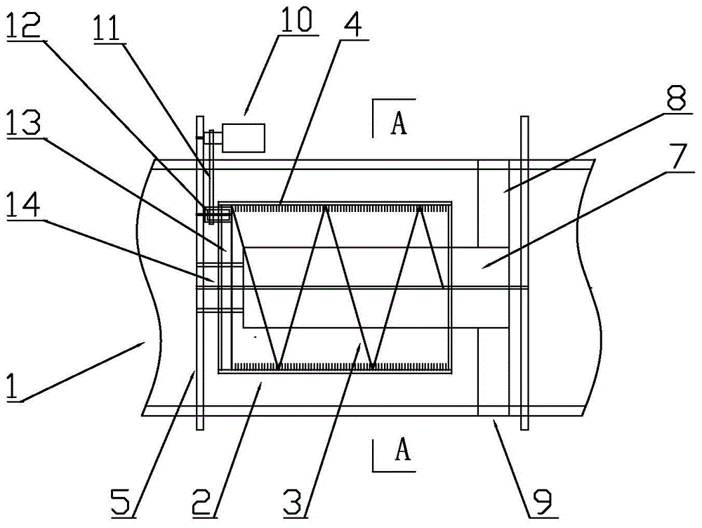
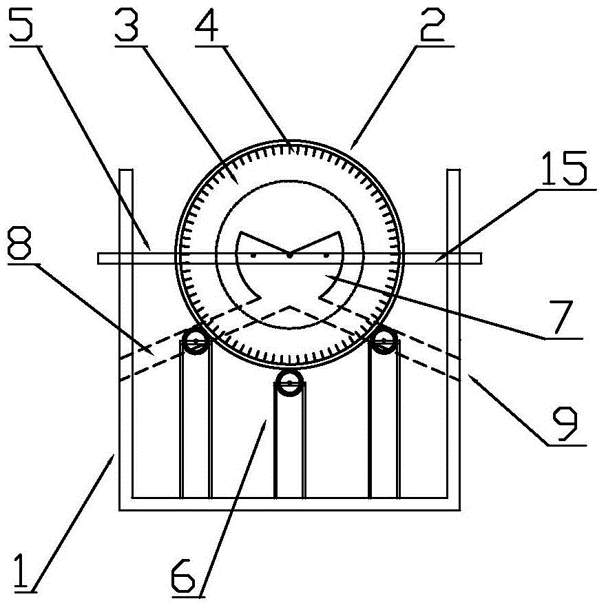
[0023] according to figure 1 and figure 2 , the present invention provides a sewage push-flow debris separator, comprising a sewage flow channel 1, a net cylinder 2, a spiral plate 3, a hanging needle 4, a fixing frame 5, a net cylinder roller frame 6, a debris support plate 7, a miscellaneous Thing chute 8, sundries outlet 9, driving motor 10, transmission belt 11, toothed roller 12, inner rack 13, connecting rod 14, water level line 15.

[0024] The sewag...


PUM


Abstract

The invention discloses a sewage flow-pushing sundry separator. The sewage flow-pushing sundry separator comprises a sewage flow channel, a mesh cylinder, a helical plate, hanging needles, fixed frames, mesh cylinder roller frames, a sundry support plate, sundry slideways, sundry discharge openings and a driving motor. The fixed frames are fixedly arranged on the two sides of the sewage flow channel, and the mesh cylinder roller frames are fixedly arranged at the bottom of the sewage flow channel; the mesh cylinder is assembled on the mesh cylinder roller frames in a rolling mode, the helical plate is arranged inside the mesh cylinder, the inner wall of the mesh cylinder is covered with the hanging needles in the radial direction, an internal rack is arranged in the mesh cylinder and connected with a tooth roller in a meshed mode, the driving motor is arranged outside the sewage flow channel, and the driving motor is in power connection with the tooth roller through a driving belt; the sundry support plate is arranged in an inner cavity of the mesh cylinder, and the sundry slideways and the sundry discharge openings are transversely arranged at the ends of the sundry support plate. According to the sewage flow-pushing sundry separator, the mesh cylinder is combined with the sundry support plate, sundries are separated through the hanging needles, flow pushing is achieved through the helical plate, the service life is long, and flow pushing and sundry separating effects are good.

Description

technical field [0001] The invention relates to the technical equipment field of sewage treatment, in particular to a sewage push-flow sundry separator. Background technique [0002] With the continuous development of industrialization and urbanization, the country continues to increase the intensity of industrial wastewater and domestic sewage treatment, and the scale of sewage treatment plants is becoming larger and larger. Sewage pushers are key equipment for sewage treatment. Sewage pushers Widely used in low-speed push flow in sewage treatment plants, it is an ideal choice for water circulation mixing equipment in sewage treatment plants such as nitrification, denitrification and phosphorus removal; usually sewage treatment requires continuous operation, and the flow of sewage at specific process nodes must be guaranteed , so as to ensure that the overall effect of sewage treatment is up to standard, so the effect and equipment quality of sewage pushers are required to ...

Claims


Application Information

Patent Timeline
Patent Type & Authority Applications(China)
IPC IPC(8): C02F1/00
Inventor 赵敏敏
Owner 苏州市和源环保科技有限公司
Why Eureka
Try Eureka