An electroluminescent device and its manufacturing method
A technology of electroluminescent devices and light-emitting layers, which is applied in the direction of electric solid-state devices, semiconductor/solid-state device manufacturing, electrical components, etc., can solve the problems of reflected light energy loss, etc., and achieve the effect of shortening the propagation distance and reducing the degree of energy attenuation
- Summary
- Abstract
- Description
- Claims
- Application Information
AI Technical Summary
Problems solved by technology
Method used
Image

Examples
Embodiment 1
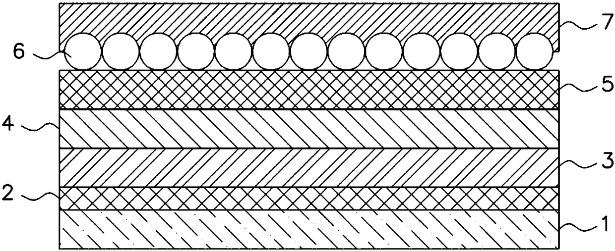
[0049] The present embodiment is an electroluminescence device, and its manufacturing method comprises:
[0050] (1) Cleaning of the ITO anode glass substrate: Use deionized water and ethanol to perform ultrasonic treatment on the ITO anode glass substrate in sequence. Cleaning treatment under oxygen plasma for 15 minutes;
[0051] (2) Fabrication of the hole injection and transport layer: in air, spin-coat PEDOT:PSS on the cleaned glass substrate at a speed of 2500rpm, and the spin-coating time is 50s; after the spin-coating is completed, anneal at 150°C in the air 30min, form the PEDOT:PSS layer (i.e. the hole injection layer), then on the PEDOT:PSS layer, spin-coat PVK chlorobenzene solution (concentration is 24mg / ml) with the rotating speed of 2000rpm, spin-coating time 60s; into the glove box, at N 2 Anneal at 150°C for 30 minutes in the atmosphere to form a PVK layer (ie, a hole transport layer);
[0052] (3) The making of quantum dot luminescent layer: quantum dot is...
Embodiment 2
[0059] The present embodiment is an electroluminescence device, and its manufacturing method comprises:
[0060] (1) cleaning of ITO anode glass substrate: same as embodiment 1;
[0061] (2) The making of hole injection and transport layer: same as embodiment 1;
[0062] (3) The making of quantum dot luminescent layer: same as embodiment 1;
[0063] (4) The making of electron injection and transport layer: same as embodiment 1;
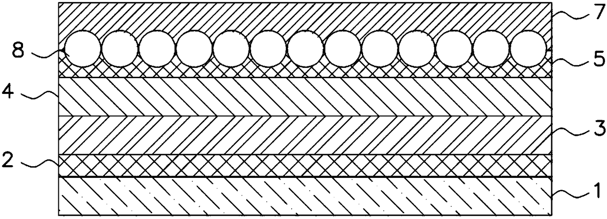
[0064] (5) The making of conductive particle layer: the ZnO nanocrystal of the band trioctylphosphine oxide ligand that particle diameter is 100nm is dispersed in toluene, obtains the ZnO toluene solution that solid content is 200mg / ml, on electron transport layer with The ZnO toluene solution was spin-coated at a speed of 2000rpm, and the spin-coating time was 60s, and a conductive particle layer was formed after drying;
[0065] After the conductive particle layer is made, use a step meter to measure the surface roughness of the conductive partic...
Embodiment 3
[0068] The present embodiment is an electroluminescence device, and its manufacturing method comprises:
[0069] (1) cleaning of ITO anode glass substrate: same as embodiment 1;
[0070] (2) The making of hole injection and transport layer: same as embodiment 1;
[0071] (3) The making of quantum dot luminescent layer: same as embodiment 1;
[0072] (4) The making of electron injection and transport layer: same as embodiment 1;
[0073] (5) The making of conductive particle layer: be that the ZnO nanocrystal of the band trioctylphosphine ligand of 200nm is dispersed in toluene with particle diameter, obtain the ZnO toluene solution that solid content is 100mg / ml, on electron transport layer with 2000rpm Spin-coat this ZnO toluene solution at a rotating speed of 60 seconds, and form a conductive particle layer after drying;
[0074] After the conductive particle layer is made, use a step meter to measure the surface roughness of the conductive particle layer, and the roughne...
PUM
 Abstract
Description
Claims
Application Information
 - R&D
- Intellectual Property
- Life Sciences
- Materials
- Tech Scout
- Unparalleled Data Quality
- Higher Quality Content
- 60% Fewer Hallucinations
Browse by: Latest US Patents, China's latest patents, Technical Efficacy Thesaurus, Application Domain, Technology Topic, Popular Technical Reports.
© 2025 PatSnap. All rights reserved.Legal|Privacy policy|Modern Slavery Act Transparency Statement|Sitemap|About US| Contact US: help@patsnap.com