
Remote bridge vibration monitoring system and method

A vibration monitoring system and bridge technology, applied in the direction of measuring devices, measuring ultrasonic/sonic/infrasonic waves, instruments, etc., can solve the problems that it is not easy to realize the supply of electric energy and the measurement cannot be carried out, so as to increase the applicable range and reduce the environment and Geographical restrictions, the effect of simple structure

Active Publication Date: 2016-09-28
秦皇岛市地方道路管理处
View PDF18 Cites 9 Cited by
  • Summary
  • Abstract
  • Description
  • Claims
  • Application Information

AI Technical Summary

Problems solved by technology

However, the device can only receive the vibration information of one point. When multi-point measurement is required, multiple sets of the device are required to be used together.
[0006] In addition, the current measuring equipment is only suitable for application in places where power supply is easy. In some remote areas, because it is not easy to realize the supply of electric energy, the measurement cannot be carried out. Therefore, it is necessary to invent a measuring device that can supply power by itself to avoid environmental damage Difficult and affect the measurement

Method used


Image

  • Remote bridge vibration monitoring system and method
  • Remote bridge vibration monitoring system and method
  • Remote bridge vibration monitoring system and method

Examples


Embodiment Construction

[0039] The present invention will be further described below in conjunction with the accompanying drawings and embodiments.

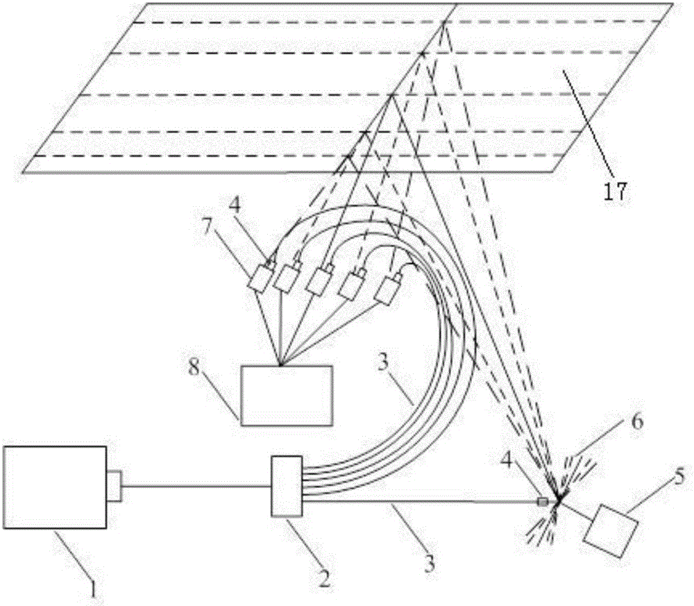
[0040] Such as figure 1 As shown, the laser measuring device of the remote bridge multi-point vibration monitoring system of the present invention comprises a laser transmitter 1, an optical fiber coupler 2, an optical fiber 3, a stepper motor 5, a plane mirror 6, an optical fiber collimating mirror 4, a photodetector 7 and Signal sending module 8.

[0041] The laser transmitter 1 emits the first beam of laser light, hits the fiber coupler 2, and then disperses into multiple beams of laser light. The first beam of laser light is irradiated on the plane mirror 6 through the optical fiber 3, and the laser beam is reflected on the plane mirror 6. The reflected laser beam is exactly Illuminated on the underside of the bridge 17.

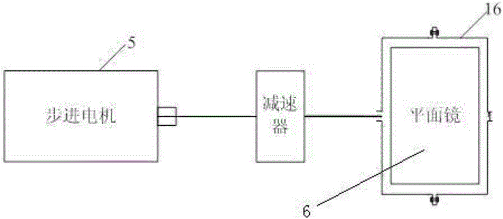
[0042] Such as figure 2 As shown, the plane mirror 6 is controlled by a stepping motor 5, and the plane mirror 6 is fixed on...


PUM


Abstract

The invention provides a remote bridge vibration monitoring system, and the system comprises a laser emitter, an optical fiber coupler, optical fibers, a stepping motor, a plane mirror, an optical fiber collimating mirror, photoelectric detectors, and a signal transmitting module. The laser emitted by the laser emitter is divided into a plurality of laser beams through the optical fiber coupler, wherein the first laser beam irradiates on the rotatable plane mirror and is reflected by the plane mirror, and the reflected mirror irradiates the bottom surface of a bridge to form a line. The second laser beam is transmitted to a plurality of photoelectric detectors through optical fibers. The photoelectric detectors also receive scattered laser signals from the bottom surface of the bridge, and enable the signals received from the optical fibers to be transmitted to the signal transmitting module. The invention also provides a remote bridge vibration monitoring method. The system and method can achieve no contact with the bridge, can employ a solar cell to supply power, and can achieve the self-sufficiency of electric energy. Moreover, the system is simple in structure, and is easy to install.

Description

technical field [0001] The invention relates to a monitoring system, in particular to a vibration monitoring system and a vibration monitoring method for remote bridges. Background technique [0002] The vibration detection of the bridge is an important index to test the safety of the bridge. The vibration information of the bridge can reflect the safety of the bridge structure and the durability of the bridge. With the development of economy, more and more bridges are being built, so the safety monitoring of bridges is more important. [0003] At present, the detection of bridge vibration is mainly to install sensors and some measuring equipment on the bridge to measure the vibration of the bridge, but this method is easily affected by the traffic on the bridge during measurement, and is very dangerous. The purpose of non-contact long-distance measurement can be achieved through laser, and multi-point measurement can be realized, which can more accurately reflect the vibra...

Claims


Application Information

Patent Timeline
Patent Type & Authority Applications(China)
IPC IPC(8): G01H9/00
CPCG01H9/004
Inventor 刘清华陶良臣章海龙尹进王志君张磊汤洪波寇胜张武
Owner 秦皇岛市地方道路管理处
Learn More